A friend of mine got a JVC TM-A170G which is a nice 17″ pro monitor with 750TVL. Unfortunately the monitor “only” has composite and S-Video inputs, so we talked about RGB modding it, which I took on as a task 🙂 Opening it up, it is apparent that is very close to being identical to the TM-H1750CG and its siblings.
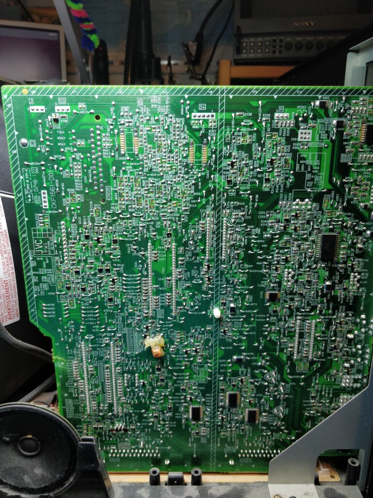
The IC of interest is IC501, the big 56 pin IC almost at the middle, a then little to the left in the above picture. This is the jungle IC, the JVC common TA1276AN, and as always there are pin numbers marked on the boards, so it’s rather easy to find the pins we need to deal with. We need to get YS2 (pin 32) switchable to 5V, however it is pulled to GND by R554 (it sits to the right of the leg, along with C551-C553), a 0 Ohm resistor (which forces internal RGB mode, meaning deduced from composite, S-Video or YUV). So replacing this with a 10K Ohm or alike resistor makes a proper pulldown so composite is still available. The capacitors C551-C553 also needs to be removed as they are connected to the RGB pins (R/35, G/34, B/33) and would otherwise filter the video signals to GND.
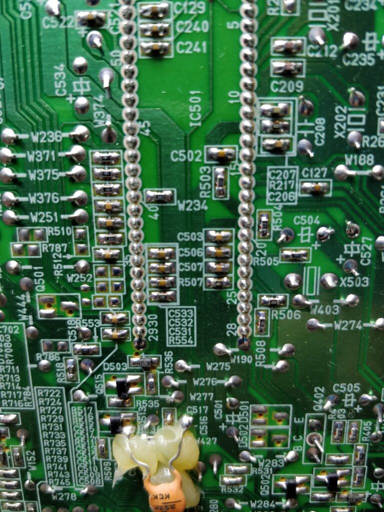
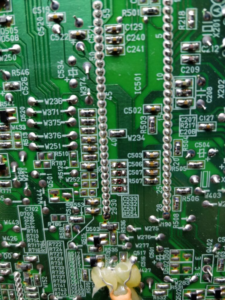
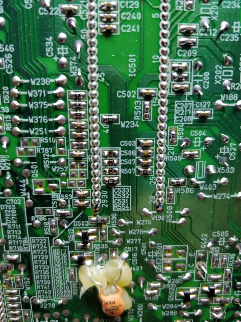
Now we need to attach cables to the appropriate pads (or directly to the pins). For RGB switching, the rightmost pad of R510 (which is not mounted) is a good place to solder a wire to. The three empty pads right next to the pins are good for the RGB lines.
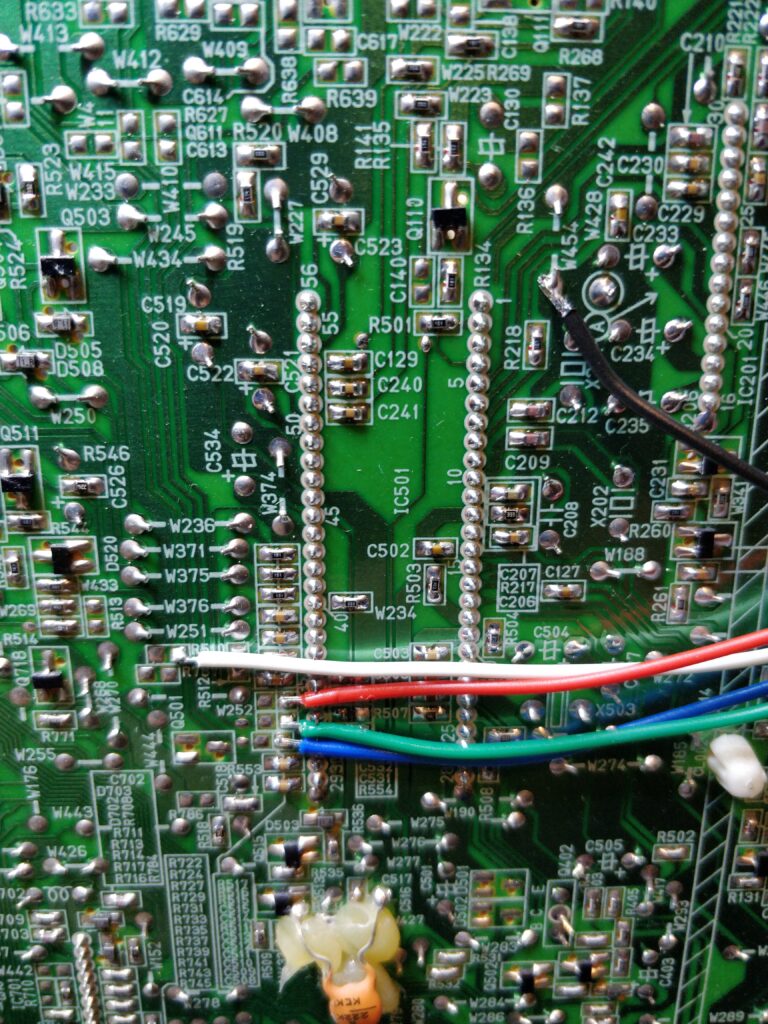
GND was also attached to whatever suitable point
These lines cannot be directly attached to the input connectors. They need to be attenuated, DC biased and terminated properly. Here comes the same drawing as I’ve used in most of my other posts.

I attach the RGB select/blanking pin to SCARTs blanking pin, which is 3-5V for RGB sources (pin just has to be more than 0.75V to select RGB). If SCART is not used, one could attach a switch somewhere to select it, use the voltage from the switch that selects inputs or something else.
We need to have sync getting in also. Most guides say that this should be inserted (as CSYNC) to pin 15, which is also possible, but I prefer to use one of the BNC input pins so it is properly routed (and saves some components, as we then don’t need the circuit from above on the sync line also).
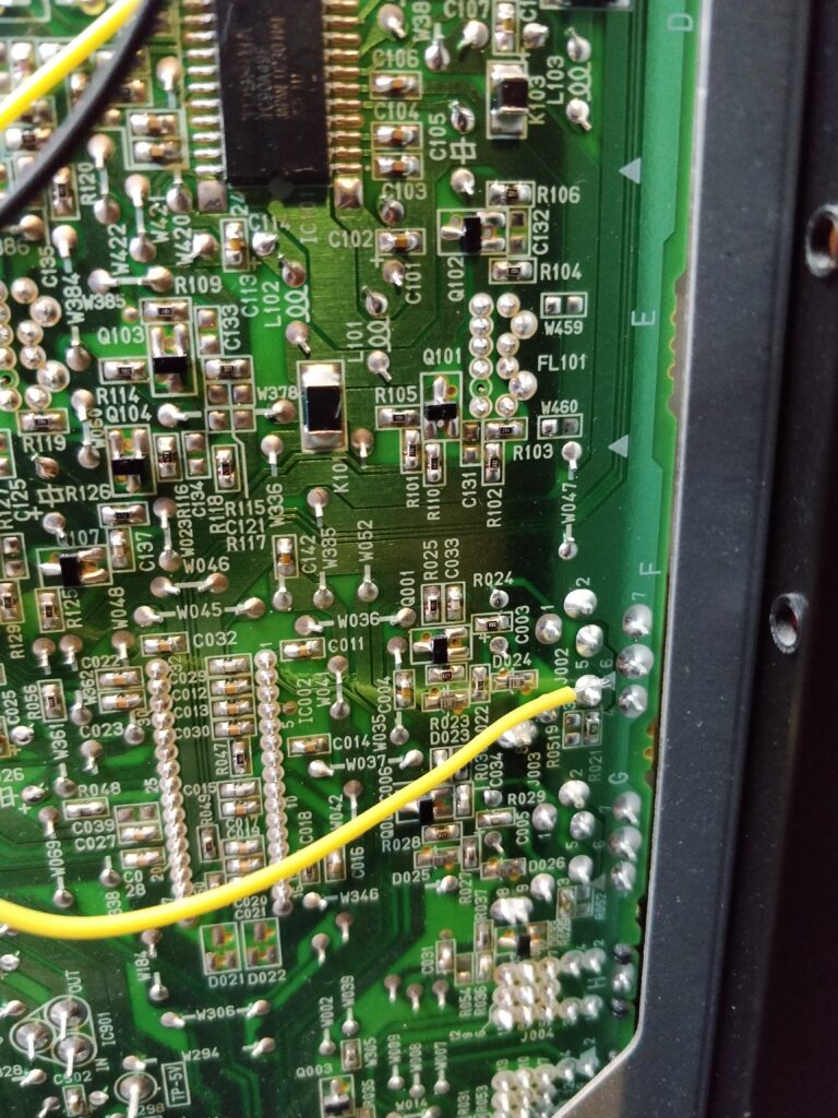
This monitor also has audio. This is injected (as mono) to input A pin. I forgot to take a picture of this, but with a multimeter, it’s easy to find the pin (it’s a bit further south of this pin, and somewhat covered by the case, but not unreachable in any way. Mono should be mixed properly from stereo if needed, this can be done with a circuit like this (if from SCART, otherwise insert left and right channels instead).

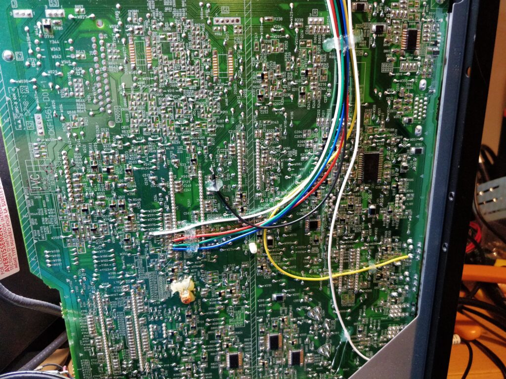
Now all the circuits can be dangling components, small boards or whatever, and you might notice no components are on the picture above. I’ve started to use a small board that breaks out SCART to the appropriate signals, AND carry the circuits for the signal attenuation (or passthrough for sync) and for stereo-to-mono. At the same time it has RCA out for audio passthrough, and a switch to select the audio coming to the monitor or to the RCAs. You can find the board here on OSHPark.
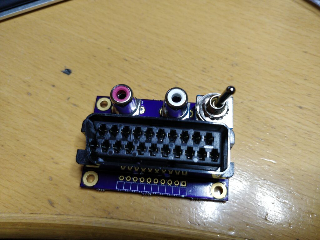
At the same time I designed a 3D printable bracket for the board which can be attaced the the monitors top ventilation without drilling. You can find the STL file and original FreeCAD files here.
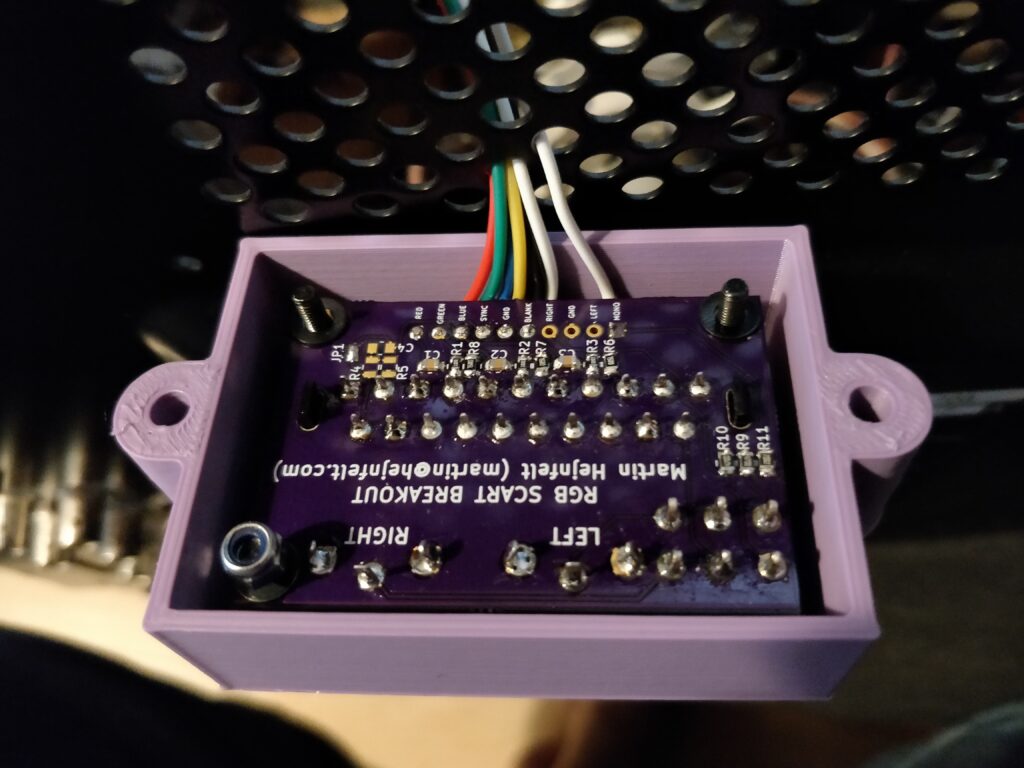
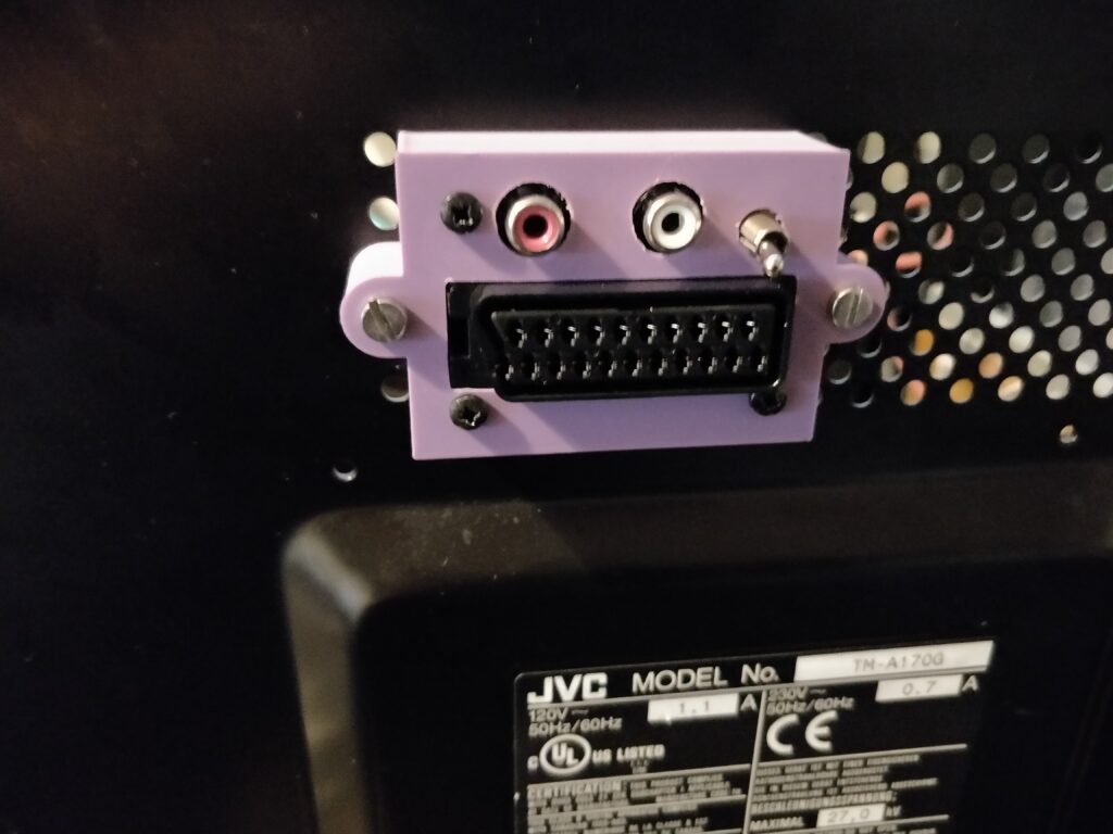
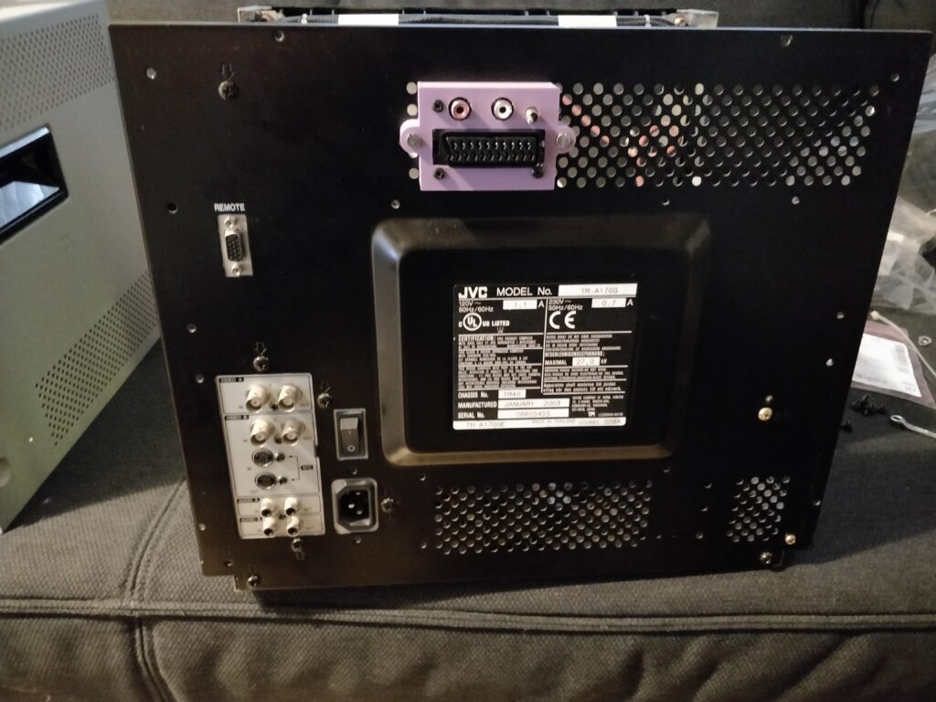
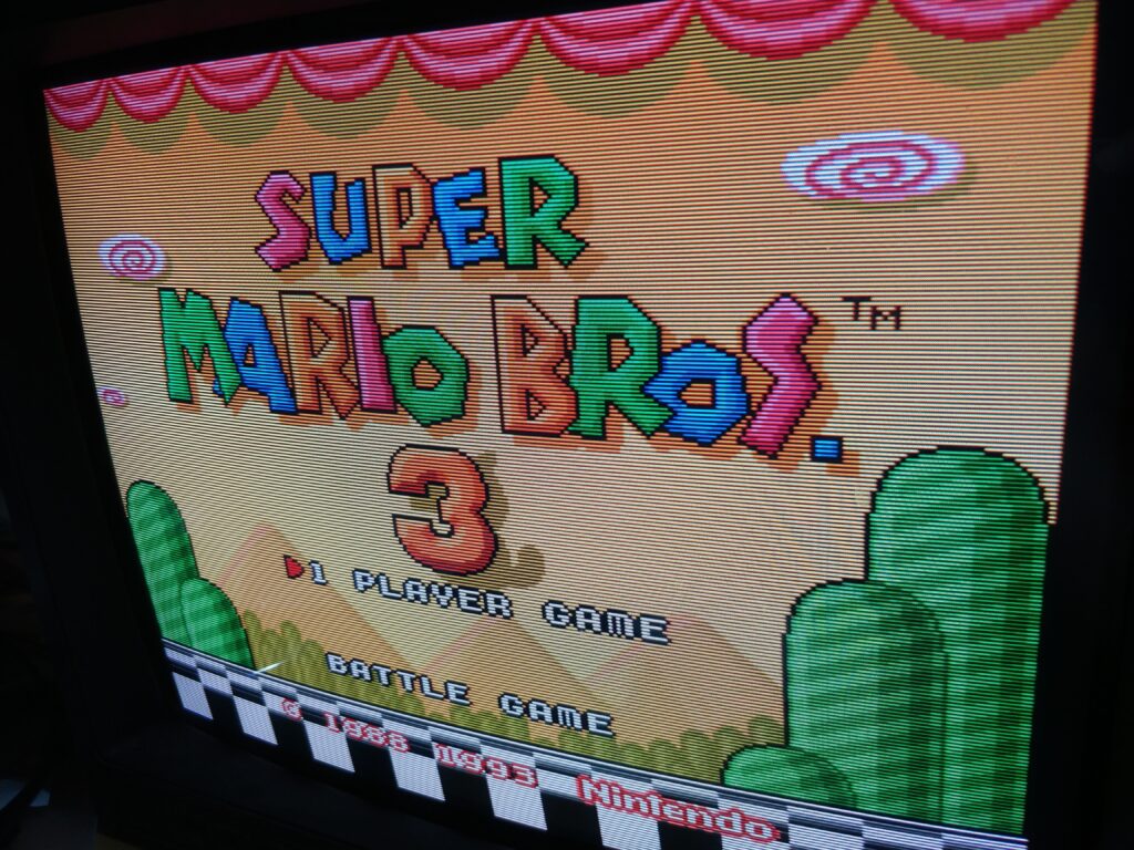
And voila, RGB modded TM-A170G. Here are some pictures (taken with phone, so real life is *much* better):


