– or “How my love for logic analyzers is re-affirmed”
This is both a documentation project as much as a reference for myself. I will update this as I figure stuff out, so this article is in no way “final” (yet). I’ve decided to release it as openly as possible, mostly to maybe get feedback and ideas, but also to show the world that reverse engineering projects of the BKM-68X *is* being done. Please send me any ideas or thoughts about the project (martin@hejnfelt.com) but please no “When is it done?” and alike. It might come “soon”, it might come never.
In the current world of CRT enthusiasts working with professional monitors, there are few input cards that has a more elusive status than Sony’s BKM-68X, the analog RGB/YPbPr input card for Sony’s BVM-A series. This card is the only way to get analog component signals into the BVM-A series, at least without any converters. The BVM-A series came very late in the CRT era, and thus lot of production had already shifted to digital formats and utilized digital formats like (HD)SDI as the transport, instead of analog formats. This seemingly means that there are very few BKM-68X in existence (the talks are around 1000 units) in comparison to the number of available BVM-A’s, which then usually sports the (HD)SDI card BKM-62HS and maybe the BKM-61D (SDI and composite/S-Video). The scarcity of the BKM-68X means that they often sell for more than $2000 a piece, if they are even available. Given that the A-series are young monitors, they are desirable given that their tube-time is often quite low.
So, in the world of retro-gaming, digital formats, especially not SDI are usually not desired, while young tubes, high TVL and RGB is are. Shelling out $2000+ for a input card is however insane for many, which often leaves BVM-A monitors undesired (there are some other issues with the 68X/BVM-A, especially sync wise, but forget about that for now). In general increasing the availability and decreasing the costs of the BKM-68X, would be helpful for the retro-gaming community, which makes it a good candidate for reverse-engineering.
When I released the reverse engineered BKM-129X card, a lot of people asked me about the BKM-68X, to which I normally replied “Forget it”. This was because the design is *massive*. The card has so many components that it looks like the surface of the Death Star, and if some X-Wings appeared trying to find an exhaust pipe to bomb, nobody would really find it weird. At the component level, Sony has also blessed us with black-box units like a FPGA plus a CPLD at the same time, so yay!


One night however, my life was apparently going so slow, that I ended up looking at the service manual for the card (most likely to avoid watching Dora the Explorer, Bob the Builder or alike), which sports the full block diagram and schematics to the card. By looking at the signal names for what is seemingly thrown around on the IO connectors (of which there are two 100-pins) and by looking at the signal paths, it made me believe that the card is seriously over-engineered, at least in the context of retro gaming, and that many features can be simply omitted, if the goal is not a replica but a basic “alternative” which supplies RGB/YPbPr to the A-series, and that’s it. It’s my belief that this would be beneficial to 95% of the A-series owners, of which I suspect very few are professional video editors, and many retro-gaming enthusiasts.
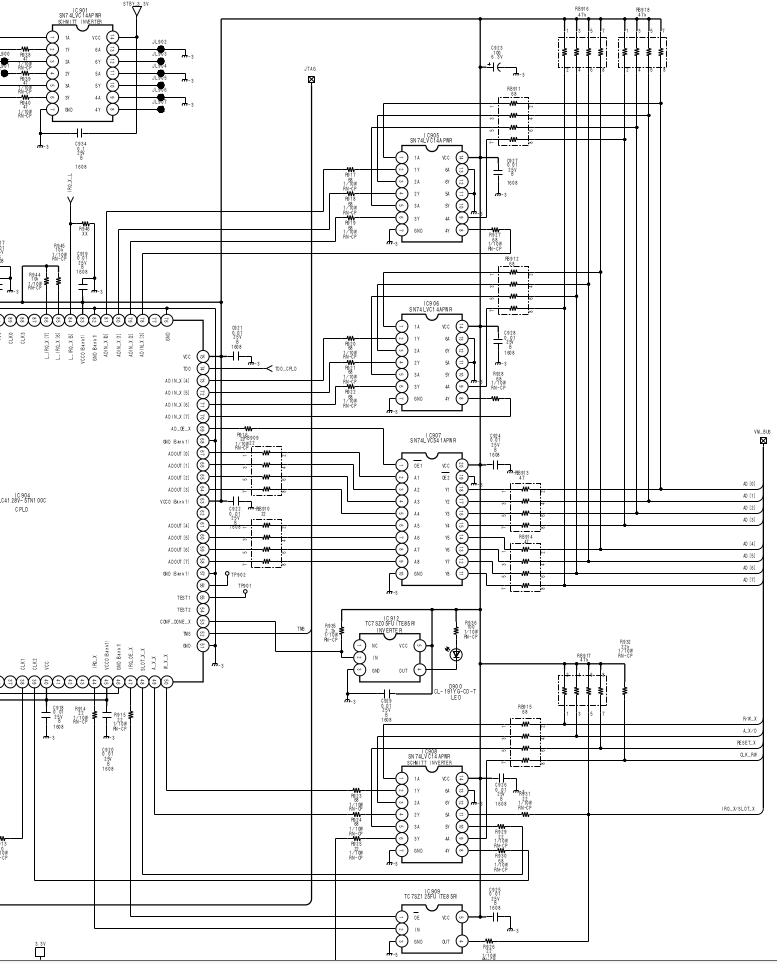
What really made me interested was this part of the block diagram:

Plus the part of the video signals:

Now the CPLD interface suggests a quite standard parallel interface of a shared address/data bus, plus the video signals seemingly are normal analog RGB/YPbPr along with separate horizontal and vertical sync signals.
All around the board are signals which are generally in the same “vicinity” to the ones of the BKM-129X, namely: VIDEO_OE_X (video output enable, active low), INT/EXT_X (internal/external sync, active low), HD/SD_X (high definition/standard, active low) and so on. There is some circuitry that seemingly seems able to do some “magic” to the input, like an aperture generator (I have no idea what that should be doing) but in the end, I this seems to be non-vital. In general though, looking at the signal paths for the RGB signal paths, they basically do through some filtering and buffering, with some different paths (filtering orders, delay lines) selectable by the HD/SD_X signal. It all ends up in the IC486, which is a AD8075ARUZ which is a 500MHz 6dB video buffer, that is still easily obtainable (and should most likely also be replacable by something like the THS7374).
As the address/data bus should be able to be “eavesdropped” on, exactly like the SPI-like bus for the BKM-129X, it is my firm belief, that a viable alternative can be created.
Of course reading the contents of the EEPROM for at least the FPGA could be possible, but using the data would be against the law in many countries, and in the end also still require the same FPGA unless the bitstream was then reverse-engineered.
Accessing the hardware
To be able to actually do such a project, the original hardware is strictly necessary. Fortunately I was gifted a BVM-A20F1M with a BKM-15R for the project. The BVM didn’t have the BKM-68X, but it did have the BKM-62HS, so it was a start, even because the 62HS’s digital signals still end up as analog video coming into the monitor. Technically, this would mean that even just ending up being able to impersonate a 62HS might give a “workaround” card. However seemingly the card supplies YPbPr to the monitor, plus there are some horizontal scan rate “issues”. Jumping a bit in time, I was lucky to get an original BKM-68X donated to the project, which opened up the possibilities to make a board much closer to “what we want”.
To eavesdrop on the communication, I developed a small “breakout” board that could be inserted between the monitor and the card, which breaks out each 100-pin connector:
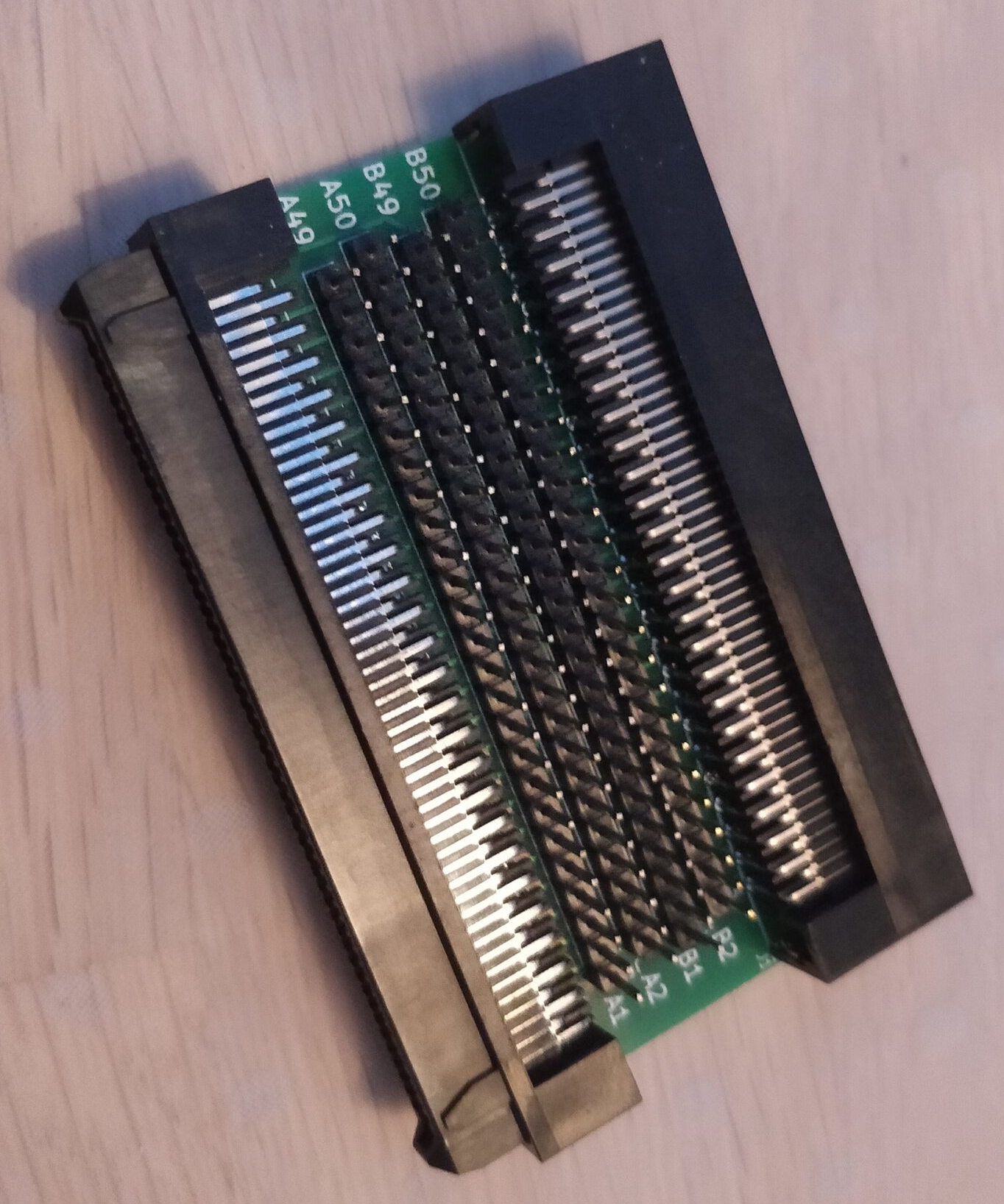
The connector is a JAE TX24-100R-LT-H1E (mating with TX25-100P-LT-H1E). This card allows me to easily attach the probes of my logic analyzer and listen in on how the card and monitor speaks to each other, exactly how I also dealt with the BKM-129X card. I still need to solder a couple of wires onto miscellaneous spots of the board, as to find the command sequences for the different “options” (internal/external sync, RGB/YPbPr etc.). This is kinda fear inducing when you start to solder onto a $2000+ card. Luckily though, there are some resistors at all points of interest that can be used:
VIDEO_OE_X @ R522
INT/EXT_X @ R885
HD/SD_X @ R838
RGB/COMP_X @ R840
Also to be sure how the data exchange works I needed to figure out when the data bus is driven by the CPLD and when it is driven by the monitor. As can be seen in the service manual, the CPLD has 8 address/data (A/D) lines in and 8 A/D lines out, both “buffered”, but the A/D out lines, has an “output enable” signal (AD_OE_X) attached to it. The same goes for the IRQ_X signal which is tied to the IRQ_X/SLOT_X signal, through a buffer, which is enabled by IRQ_OE_X signal. These signals can be observed at:
IRQ_X @ R914
IRQ_OE_X @ R915
AD_OE_X @ R916
The signals of interest are thus:
AD[0:7] (8 bits/1 byte) – The address or data byte being transmitted
A_X/D – A/D byte is address when this is low, or data when it is high
R/W_X – Data is read when this is high or written when low
CLK_RW – Data is latched on the this, seemingly on positive edge
AD_OE_X – Address/data bus is controlled by CPLD when this is low
IRQ_X/SLOT_X – Seemingly when this is low, the monitor interrupts the card *OR* when IRQ_OE_X and IRQ_X is low, the card interrupts the monitor
RESET_X – Reset the card on low
So 15 signals, plus the 4 internal-card signals (VIDEO_OE_X etc.) meaning 19 signals. To do all this at once, I had to upgrade my logic analyzer to more channels, so I bought one of DreamSourceLabs DSLogic U3Pro32 and srsly, it’s awesome. If you need a cross platform logic analyzer, I can recommend this (I use Ubuntu/Linux as my primary OS).
As with the BVM-D9 and D14, the monitor starts speaking with the card already at standby-power (when the mains-switch on the back of the monitor is flicked), so I set the logic analyzer to sample at 20 MHz for 50 seconds from when I flicked the switch, and ho-lee-phuck, these monitors speak, jesus christ.
Analyzing the data
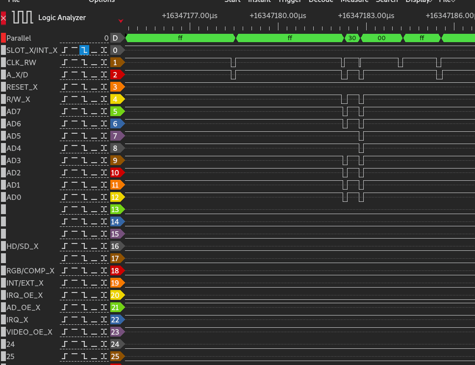
So here’s a screenshot of DSView of the data:

So first, again, there’s a lot of data, and at first, I noticed that CLK_RW pulses were 50 ns (20 MHz) in width, which means when I sample at 20 MHz, I’m not upholding Nyquists Sampling Theorem, which says that to properly sample something at frequency X, you need to sample at 2*X. This means that I needed to redo my measurements at 50 MHz (next available sample speed on my analyzer) at least if I wanted accuracy in the timing between edges. Doing this showed that clock pulse widths are 40 ns so 25 MHz(!).
At first I was unsure of what to make of all this data, because according to the service manual of the monitor, each slot has a separate SLOT_X_INT_X signal *and* CLK_RW signal. This would indicate that it would only clock data to the card (with CLK_RW signal) when it was speaking to the specific card. Seemingly all these data points are clocked in, which would, at first glance, mean that all this data was bound for the card. Luckily after “working” through the data, I got an “epiphany”: The card “changes” which commands it reacts to depending on which slot it is in, and this is actually somewhat of a kicker, because it narrows the amount of data to react to considerably down. The idea can be seen here:


So first the monitor issues a 02h command, followed by 01h which asserts IRQ_OE_X (interrupt output enable, active low). Then comes FFh (which denotes a start and end of command sequences, as will be seen later). Then it issues a of 10h 03h XX (XX = 01h-07h), FFh then 02h 00h which de-asserts IRQ_OE_X again (thus seemingly allowing interrupts from the card again). Now in the first picture, it can be seen that SLOT_X_INT_X goes low in the 10h 03h 02h (where the card is in OPT1 slot), but in the second picture, it goes low during 10h 03h 03h (where the card is placed in OPT2, so the second slot). As the first slot is actually the network card (or whatever we call it), where the remote and such is placed, it makes sense that OPT1 is actually slot 2 (in the monitors sense), OPT2 is slot 3, OPT3 is then slot 4, then comes whatever the other “cards” are in 5 and so forth.
EDIT: Using my eyes, the monitor even says so 😀

When the card is in OPT1 as the only one, it reacts to commands in the 2Xh, while in OPT2, it reacts to 3Xh. The monitor does try to read 3Xh and 4Xh addresses, from time to time, but when there is no card there, nothing responds.


So all in all, we can now assume that only commands starting with 2Xh is actually intended for the card, when sifting through the data recorded when the card was in OPT1. I will generally show 2Xh commands as I’ve got most data from the card in the first slot, so in all those cases, practically the first byte could be 3Xh or 4Xh if the card was in OPT2 or OPT3 respectively.
Command format
From this it can be deduced that the general command format is like this:
First the monitor issues a FFh with AX_D low and R_WX high.
Then it writes a “command/register byte”, then an “offset” byte, and then the actual value (either read from, or written to, denoted by R_WX), and then a FFh more.
So an example as above is FFh 20h 00h 88h FFh, where R_WX is high on the last byte, meaning the monitor is reading byte 00h from register 20h, in the above example, this returns 88h.
For the two “special” commands, 02h (IRQ) and 10h (setup/init) it starts with the command, and ends with FFh.
Here is an example of a write:

So here it writes A0h to 32h 25h, so FFh 32h 25h A0h FFh.
Card identification
So first part is figuring out where the card is actually being identified. Analyzing the data from the BKM-68X, BKM-61D and the BKM-62HS shows that the first difference lies in the response of the read from 20h 00h, which responds 88h on BKM-68X, 81h on the BKM-61D and 82h on BKM-62HS. This also the first command issued to the card, before all the serial stuff and whatnot begins.
Serial number readout
Command 23h seems to read the serial. The serial must be read out from some PROM by the card internally somewhere, as I suspect the Xilinx FPGA actually contains a softcore CPU or something, because there are some “wait-states” where the monitor issues some command, then repeatedly reads some register until it turns to some value (00h), then reads another register, seemingly verifying its contents, and then repeats the process if not “accepted”. One of those registers is the serial, first byte, 23h 00h. Initially the monitor issues some commands, reads a register until it turns 00h, then reads 23h 00h, which returns 88h (like the identification register). If this is the case, the monitor re-issues the command sequence, reads the register, repeats until this register returns at least 32h, which is the first byte of the serial (just as with the BKM-129X, this is ASCII coded digits, so 32h is 2). The complete serial is then located in registers 23h 01h, 23h 02h etc. until 23h 06h as there are 7 bytes in the serial (eg. “2 0 0 1 3 3 7” would be represented by 32h 30h 30h 31h 33h 33h 37h), so:
23h 00h 32h
23h 01h 30h
23h 02h 30h
23h 03h 31h
23h 04h 33h
23h 05h 33h
23h 06h 37h
Video format settings
Command 21h seems to work on the video settings.
Register 10h (21h 10h) works on (at least) VIDEO_OE_X (video output enable, active low), INT_EXT_X (internal/external sync, low = external) and APA_ON (Aperture). The bits of the data byte I’ve identified are:
Bit 3 is VIDEO_OE_X (0 = VIDEO_OE_X -> HIGH, 1 = VIDEO_OE_X -> LOW).
Bit 2 is aperture (1 = APA_ON -> HIGH, 0 = APA_OFF -> LOW)
Bit 0 is INT_EXT_X (1 = INT_EXT_X -> HIGH, 0 = INT_EXT_X -> LOW).
Register 31h (21h 31h) is the detected video format. This detection is seemingly done by the card itself. When the card detects video, it de-asserts the SLOT_X_INT_X signal, thus interrupting the monitor, which then issues some commands, including reading this register. I’ve identified the following data byte meanings (21h 31h XXh):
00h – No video input
01h – 576i / 50 Hz (verified with EU Wii/EU PS3)
02h – 480i / 60 Hz (verified with US SNES)
03h – 576p / 50Hz (verified with EU PS3)
04h – 480p / 60 Hz (verified with EU Wii)
0Ch – 1080i / 60Hz (verified with EU PS3)
12h – 720p / 50 Hz (verified with EU Xbox 360)
13h – 720p / 60 Hz (verified with EU PS3)
I need further units to know the values for other supported, however my guess is that some of the others are:
0Bh 1080i / 50 Hz
1035i/60 and 1080i/48 I have no idea about…
Given the supported formats here:

So when the card detects an input (change) it de-asserts INT_X (which de-asserts SLOT_X_INT_X), and waits for the monitor to issue a sequence of commands.
Impersonating the BKM-68X
So to make a “clone”, there are some hardware requirements we need to meet, which does go out-of-spec compared to normal microcontroller options, namely the 25MHz I/O capability. Given that the 68X *and* the A-series are pumped full of FPGA and CPLD technology, the obvious choice is to use a FPGA.
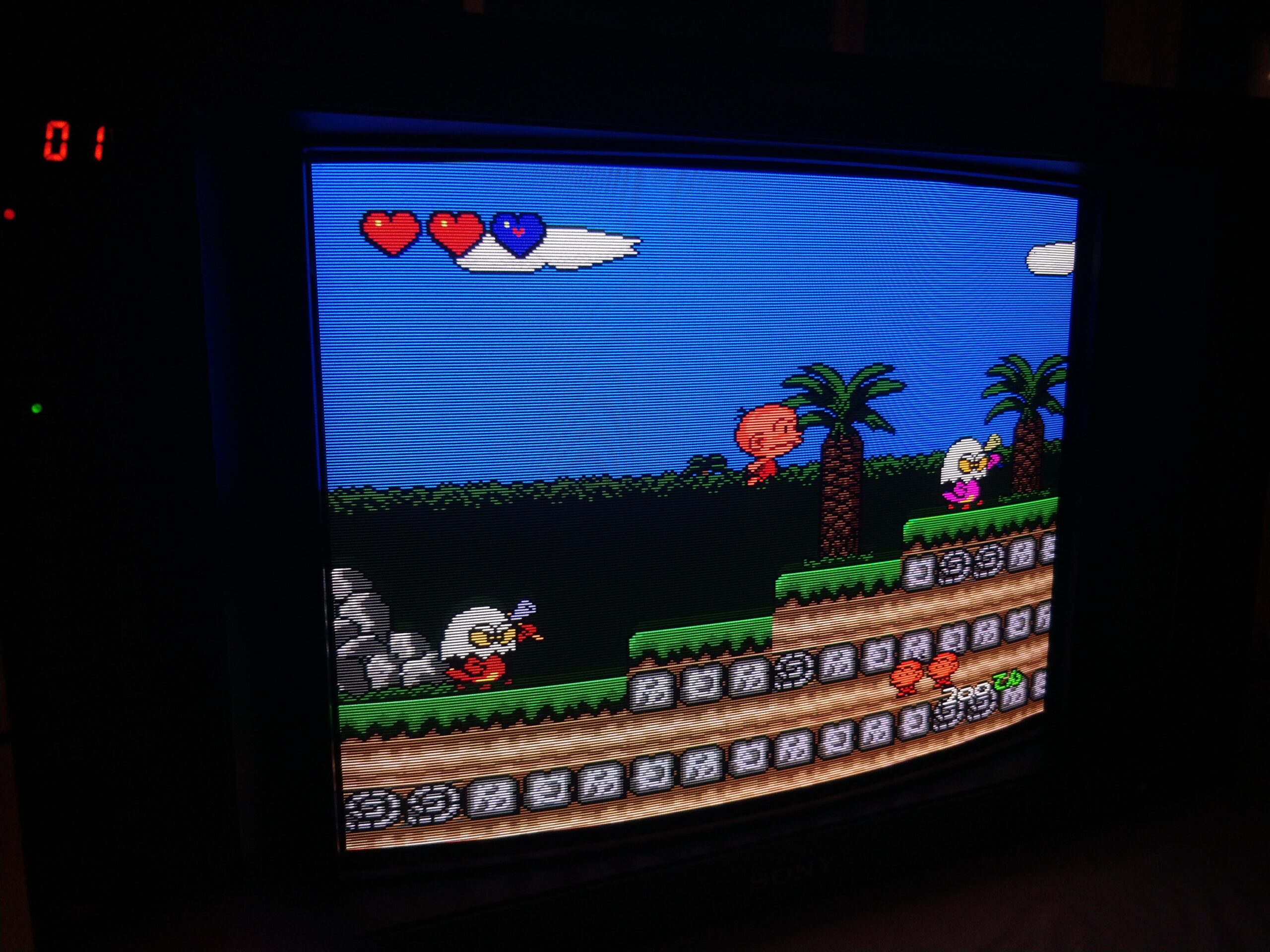
Fast forward some time, I’ll fill in the blanks at some point (everything will be open sourced), it works!

… To be continued