Since I have 8 old retro consoles/computers connected to a TV, I decided that I needed to be able to switch these on and off individually, as some console PSU’s influenced others, creating interference on the video output. Another reason was that I really did not want all these old PSUs connected all the time (who knows when these old electronics are going to burn up). So to solve it, I needed some relays capable of switching 230 VAC (this is Europe :P) and something to control them. I really wanted it to be ethernet based, in order to be able to switch them from my phone or any other external device, without hard-wiring controls directly to the power switch.
There is nothing new to this system, many others have done the same 🙂 This is just my implementation…
Anyway, to do all this, I chose a 8 port relay board similar (maybe the same?) to this:
Instead of using an Arduino or whatnot, I chose the Raspberry Pi. Mainly because I had one lying around, and because I’m familiar with it. The one I used was the ooooooold 256MB B version (first released version) and an installation of minibian (https://minibianpi.wordpress.com/) on a 1GB SD card.
Although the relay board is 5V, and the GPIO of the Raspberry Pi is 3.3V, as the inputs are active low, the 3.3V is apparently enough to keep the relay from switching. Thus we need no fancy interface voltage converting boards or whatever.
Anyway, the biggest hurdle to this whole system, is that the Raspberry Pi kernel defaults most GPIO to inputs and with an active pull-down. This sucked bad, as the system is in a rather “unstable” state until the linux system has booted and my application can “fix” the GPIO direction, causing some rather unfortunate switching of the relays on each boot, which kinda sucks when dealing with “high” voltage like 230 VAC.
But as always, this can be dealt with, and rather elegantly, by using device tree. Seems that the Pi reads a file called dt-blob.bin located on the “/boot” partition of the SD card, IF IT IS THERE (which it is not by default). However, this file can be created (yay) and changed so we can deal with HOW the default pins are set, to accomodate to my usage here. Long story short, I downloaded the dt-blob.dts file from the Raspberry Pi repo
wget https://www.raspberrypi.org/documentation/configuration/images/dt-blob.dts
and added these lines to the section representing my Pi (being the first):
 pin@p1 { function = "output"; polarity = "active_low"; startup_state = "inactive"; termination = "pull_up"; };
 pin@p4 { function = "output"; polarity = "active_low"; startup_state = "inactive"; termination = "pull_up"; };
 pin@p17 { function = "output"; polarity = "active_low"; startup_state = "inactive"; termination = "pull_up"; };
 pin@p21 { function = "output"; polarity = "active_low"; startup_state = "inactive"; termination = "pull_up"; };
 pin@p22 { function = "output"; polarity = "active_low"; startup_state = "inactive"; termination = "pull_up"; };
 pin@p10 { function = "output"; polarity = "active_low"; startup_state = "inactive"; termination = "pull_up"; };
 pin@p9 { function = "output"; polarity = "active_low"; startup_state = "inactive"; termination = "pull_up"; };
 pin@p11 { function = "output"; polarity = "active_low"; startup_state = "inactive"; termination = "pull_up"; };
and recompiled to dt-blob.bin (as per https://www.raspberrypi.org/documentation/configuration/pin-configuration.md)
When this is working, the relays are all off (because of our pull-up) on boot.
Next thing was writing a small application to deal with the I/Os via ethernet. Long story short, I used the WiringPi library, and made a small server that accepts JSON encoded packets to get and set the I/Os. Get the awesome code here: https://github.com/skumlos/relayserver
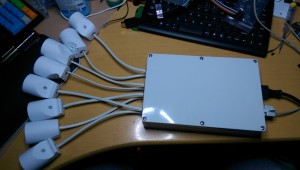
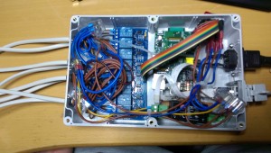
I wired up 8 230 VAC sockets to the relays, put in a hard switch to be able to “really” kill the outputs if needed, a IRM-10-5 PSU from Meanwell to drive the Pi and a chassis RJ45 plug for the networking. All in all it looks like this:
And like this on the inside

