Archive for December, 2018

Converting a T64 file to D64 in Linux (Ubuntu)

Sunday, December 30th, 2018

So I had a lot of Commodore 64 games saved as T64 “images” which is very space conserving. I however had to use these on a SD2IEC which does not support T64, so the obvious choice was to convert them to D64, although it takes more space (as each D64 is a disk image, whatever remaining space there will be, will be “slack” space). Anyways, who cares about space in the age of 100’s of GB SD cards costing $20. The “best” option I guess would be to directly extract the PRGs but I haven’t gotten to that, and this page is more or less a reminder to myself… Anyways, I started to go through the internet to find a quick solution to convert all these games, and I found a lot of different options, mainly Windows stuff that would need to run in wine and most likely be non-scriptable to extract. Some mentioned c1541 which is a part of the VICE project, which is included in many Linux distros. As I use Ubuntu, this was also the case, so apt-get install vice, and it’s in. c1541 starts a “shell” to take commands in, but they can also be given directly from the command line. So without further ado, the one-liner that converts a .T64 file to a .D64 is:

c1541 -format <DISKLABEL>,00 d64 <DSTFILENAME>.D64 8 -tape <SRCFILENAME>.T64

<DISKLABEL> should be replaced with the desired label name of the disk.

<DSTFILENAME> is the D64 filename (without the .D64 suffix).

<SRCFILENAME> is the source filename of the T64 (without the .T64 suffix).

Example (for Blue Max):

c1541 -format BLUEMAX,00 d64 BLUEMAX.D64 8 -tape BLUEMAX1.T64

This yields:

Unit: 0
Formatting in unit 8...
Writing `blue max+' ($0801 - $5618) to drive 8.
Writing `blue max spic' ($0801 - $1A1A) to drive 8.
Writing `blue max+ crazy' ($0801 - $6324) to drive 8.

3 files copied.

And we’re good! Gonna look into the direct to PRG stuff….
Fixing Samsung 2493HM not turning screen on, blue LED blinking

Saturday, December 15th, 2018

So I have a somewhat old Samsung 2493HM LCD monitor, which stopped turning on. The blue indicator LED would start blinking really short with a 1 second interval or so, but not turn solid on, and screen show an image. Sometimes if it stood blinking, it would suddenly turn on and screen would work fine, until powered off, and it would do the same again. This in my head sounded like a bad capacitor, so I disassembled the screen to investigate.

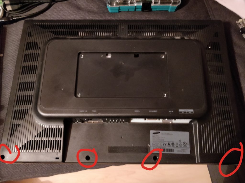
This is quite easy: Remove the 4 screws in the back on the bottom.

Remove these 4 screws

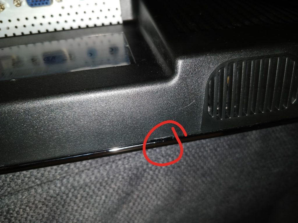
Then there’s a small notch in the bottom where you can insert something flat, and then simply pull the back cover off, use some force, it’ll be fine (hopefully).

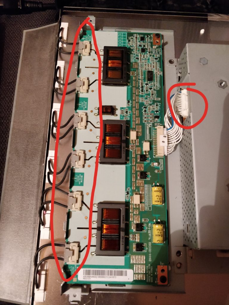
Disconnect the CCFL headers to the left by pushing the gray small connectors’ tabs and pull backwards.

Remember! This is CCFL, so high voltage shit! Disconnect the power connector to the CCFL voltage board at the metal housing to the left.

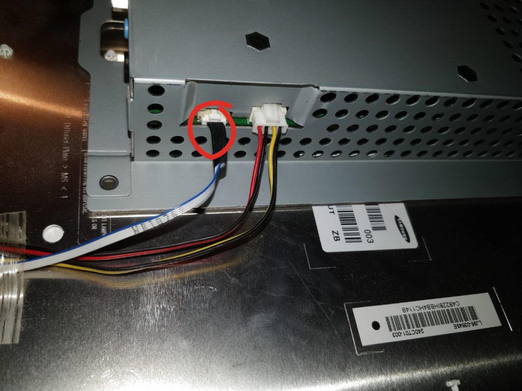
Then the two cables at the lower right. Note the one I’ve marked here is quite fragile, I broke one of the wires, so the front buttons didn’t work until I rewired it.

Turn the whole block upwards. Theres a LVDS cable going from the A/D controller board to the right, disconnect that either by the screen or by the board. You can now move the whole block freely.

I didn’t take pictures of this, apparently, but most likely you can find a disassembly guide otherwise.

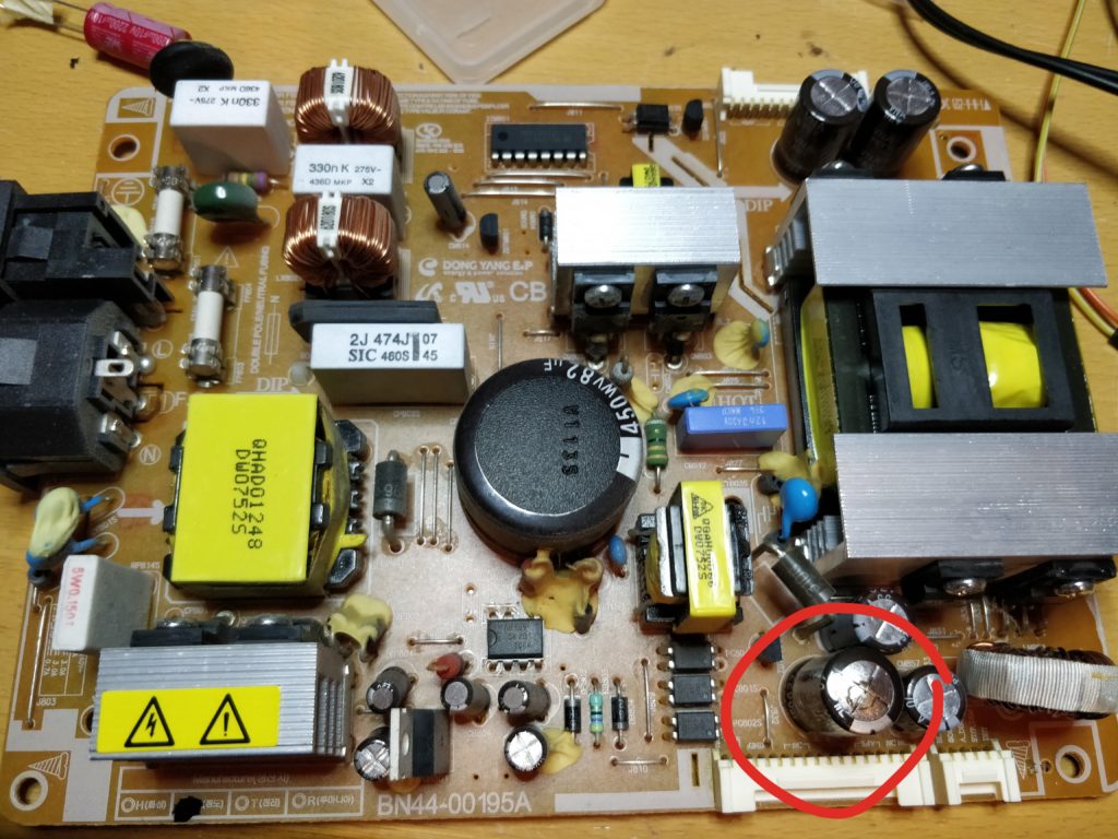
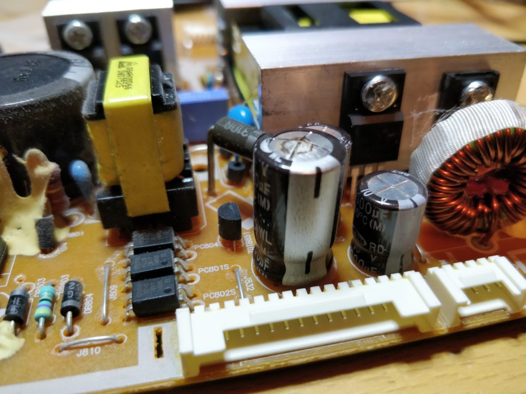
The power board has 4 screws, remove those, and the pull the ESD/grounding tape at the top to be able to remove the board. Note, again there are some high voltage capacitors here, especially a 450V/82uF sucker. Now inspecting the capacitors I found that this 2200uF/10V electrolytical capacitor (marked in red) had bulged and also it looks like it has leaked in the top.

Position of the leaked 2200uF cap.
That is one broken e-cap…

Anyways, I replaced this with a new, and presto, screen works a charm again 🙂

MFO, Multiple Frequency Oscillator

Friday, December 14th, 2018

When one is modding old gaming consoles to run both PAL 50Hz and NTSC 60Hz, often it is also required to switch oscillators to have 100% correct frequencies. This goes for machines like SNES, Master System, Genesis/Mega Drive and so on. A guy called micro made a DFO, Dual Frequency Oscillator, based on Texas Instruments’ programmable clock IC’s.

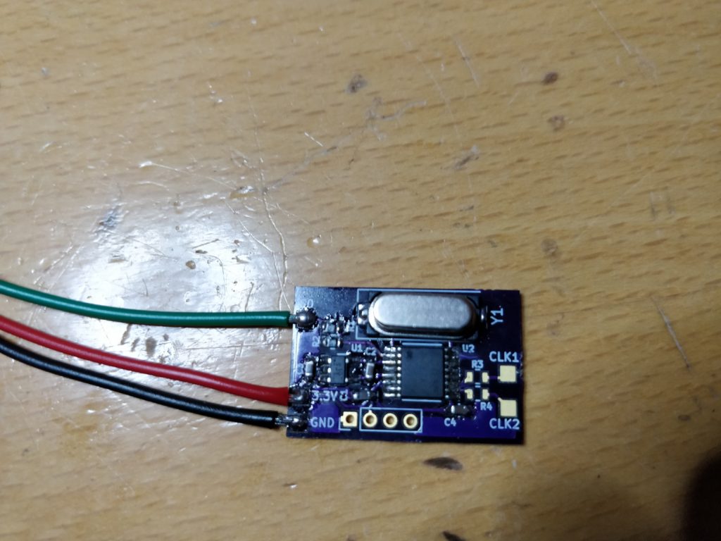
The DFO is really cool, and I’ve been using them a lot when modding. However I noticed on certain consoles, mainly the later PSX, like SCPH-750x and PSone, there are actually more than one frequency that is different from region to region. There is a Video DAC clock that needs to be changed to have proper vertical frequency and a carrier frequency for the composite video signals. Thus if running composite video on a PAL unit, in NTSC/60Hz mode, it would often be black and white, not due to missing NTSC decoding, but because the carrier frequency is 4.43MHz instead of the correct 3.58MHz. Although one could just use RGB and be done with it, but I like tinkering with this stuff, and make it _really_ working in both modes, so I decided that I wanted to take the DFO one step further, so I created the MFO. The MFO, a short for Multiple Frequency Oscillator, is more or less a copy of the DFO, but with the CDCE913 changed to a CDCE925 so I could create BOTH the 53.20/53.69MHz GPU clock _AND_ the 4.43/3.58MHz carrier frequency for the Video DAC at the same time. So the result was this:

The MFO. Multiple Frequency Oscillator

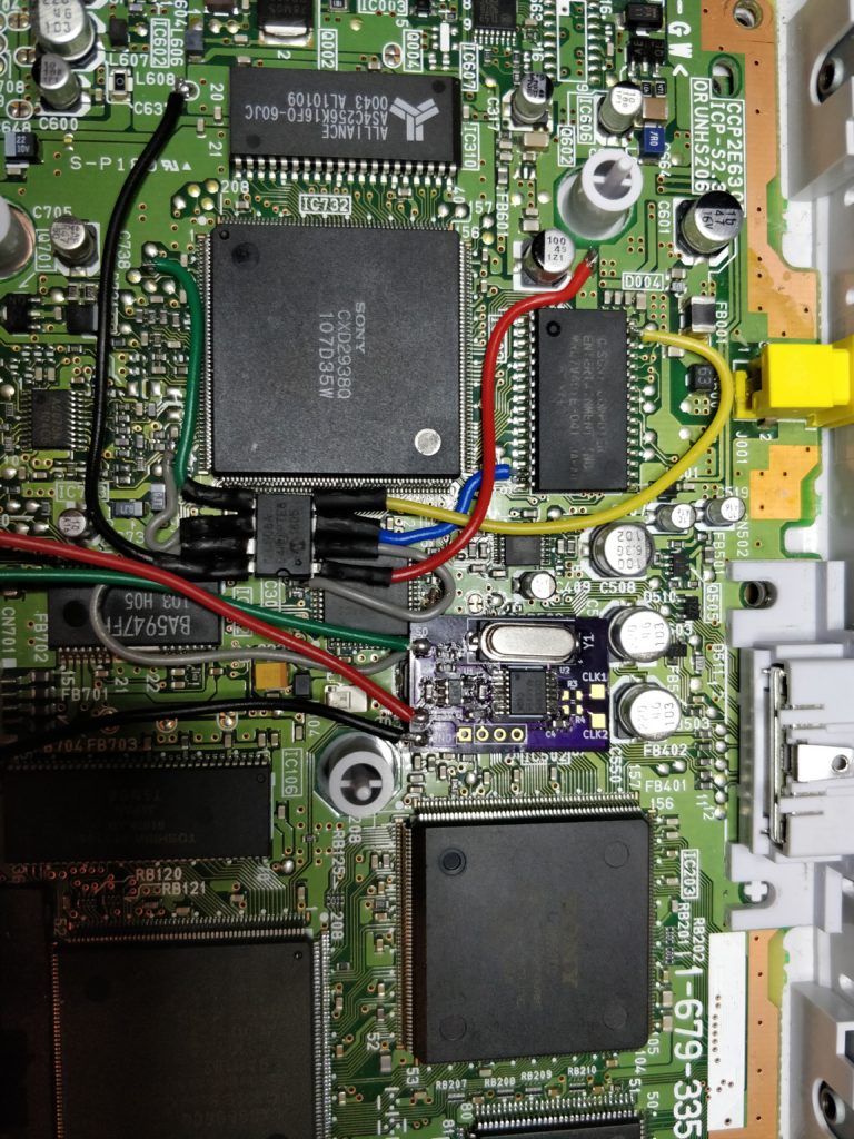
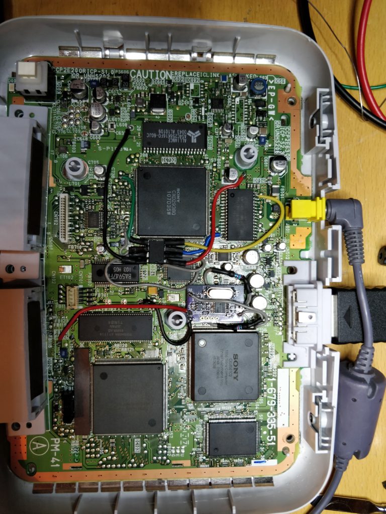
Here it is, installed into a PSone, SCPH-102, along with a onechip modchip. The two large THT resistors, was because I was out of the proper SMD resistors for the oscillator signals.

The MFO in a PSone, still missing the final connections.
The completed install.

The OSHPark design can be found here and here. The latter is a Rev. B, which is functionally identical, but with a more tiny design (space is often sparse).

Update! More details 😀

Download the hex file for the MFO for the PSX here (zip). I programmed it to the MFO by using cdceprog on a Raspberry Pi. CLK1 is the GPU clock while CLK2 is the sub-carrier.

Now injection of the signals will depend on your model, so easiest is to find the service manual and find the PLL that creates the frequencies for the system. On PSOne (and the others also AFAIK) it’s IC204. It creates 3 frequencies: One for the CPU, which is the same for NTSC and PAL, one for the GPU, (53.693175 MHz on NTSC and 53.203425 MHz on PAL), and one for the sub-carrier (3.58 MHz on NTSC, 4.43 MHz on PAL). The GPU clock goes to R205, which is a 220 Ohm resistor, close to IC203 (the GPU) pin 99. Remove R205, and inject on the pad going to the GPU by connecting CLK1 pad here. Alternatively inject on pad CL201 (still with the resistor removed of course). Replace R3 on the MFO with a 220 Ohm resistor (or use the one you just lifted). The sub carrier goes to R501 that connects to IC502 which is the Video DAC. R501 is a 2200 Ohm (2.2K) resistor, so remove that, and then on the MFO, change R4 from 18 Ohm to a 2.2K and then solder the CLK2 pad to the pad connecting to pin 15 on the DAC. The MFO’s S0 pin, which selects the frequency is then connected to pin 13 of the DAC/IC502.