Update: I’ve been told that this also works for TM-2100PN.
I got a hold of a JVC TM-1700PN, which is a 550TVL composite/S-Video monitor. As always this baby needs RGB modding! So let’s get to it.
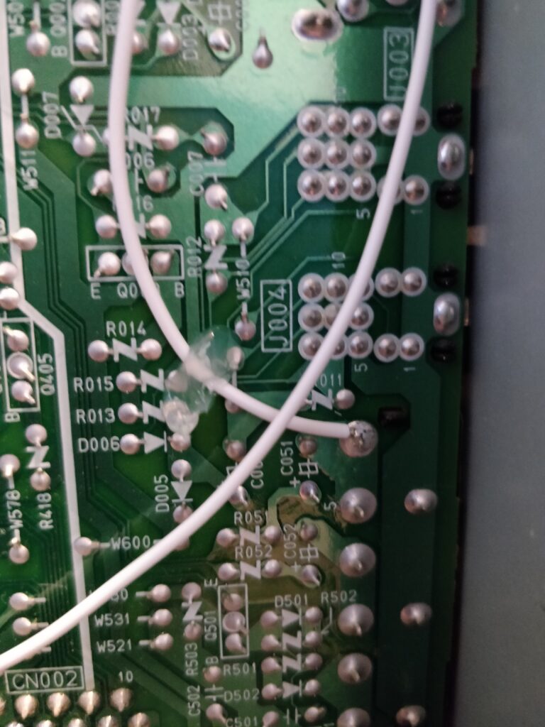
It uses a TDA8366 as the jungle IC, which has direct linear RGB input. OSD is mixed in after the jungle, so there is no need for muxing. The monitor exists in an already RGB capable version, the TM-1750PN, and actually most of the circuit is already there, but not populated. Anyways, looking at the service manual, the RGB inputs are pin 21-23 and blanking at pin 24. The pins are connected to three capacitors, C131-C133, however in the TM-1700PN they are not capacitors but simple jumpers that end up at some 22K resistors to GND. So we remove these jumpers, and this is where we inject our RGB. C131 is the blue line, C133 is the red, and C132 is the green.

Note that the RGB should be normal 0.7Vpp but 75 Ohm terminated, and with a 0.1uF capacitor before injection. I have this circuit on the SCART breakout that I use (check some of my other posts), but in general the input circuit for each line looks like this:

Sync should be added directly (no circuit) to one of the inputs, I chose directly at Input A on the PCB side of the BNC plug.

Now the next thing is getting it to blank RGB input. The TDA8633 has blanking on pin 24, however this is tied to the already present circuit of the MCU, as the pin is also used to blank the RGB output of the jungle, because OSD is added after it. This is a bit different than the other JVCs I’ve worked on, so off to the datasheet. It seems that the RGB blanking happens when pin 24 is between 0.9V and 3V. Above 4V is OSD blanking, so we need to stay within the 0.9V-3V. The monitor does this in itself by having a voltage divider between a 1.2K Ohm resistor (R725) to GND and a 1.8K Ohm resistor (R726) connected to a switch to 5V. This gives a signal around 2V, which will blank it. So to force this, we could inject 5V at that 1.8K resistor, but that is placed on the mainboard, so requires more disassembly of the monitor. Instead there is an unpopulated resistor R130 connected to the “top” of the 1.2K Ohm, so we can create a “new” voltage divider here, by added a 1.8K (I used a 2K) and inject the blanking signal through that. I at the same time added a Schottky diode as this point is where the MCU then also connects 5V for OSD blanking, and I wanted to avoid backfeeding voltage to my console. You can use more or less any diode, I choose Schottky for the low voltage drop, and of course the higher the voltage drop over the diode, the lower voltage ends up at the jungle, increasing the risk of hitting the low threshold for blanking. The circuit equivalent is something like this:

And here’s real life:

So when around 3-5V is added at the diode, it will blank to RGB. Hooray!
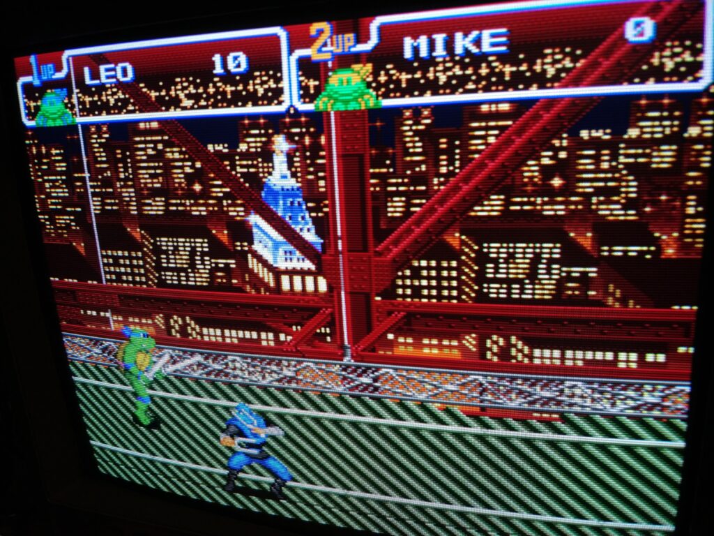
So all this is connected to the SCART breakout I’ve mentioned earlier, and presto, a fine RGB picture 🙂

The black wire is GND from the SCART board, and just goes to whatever GND point on the board.
Audio using the SCART board, audio is mixed to mono and injected at the RCA pin for input A.

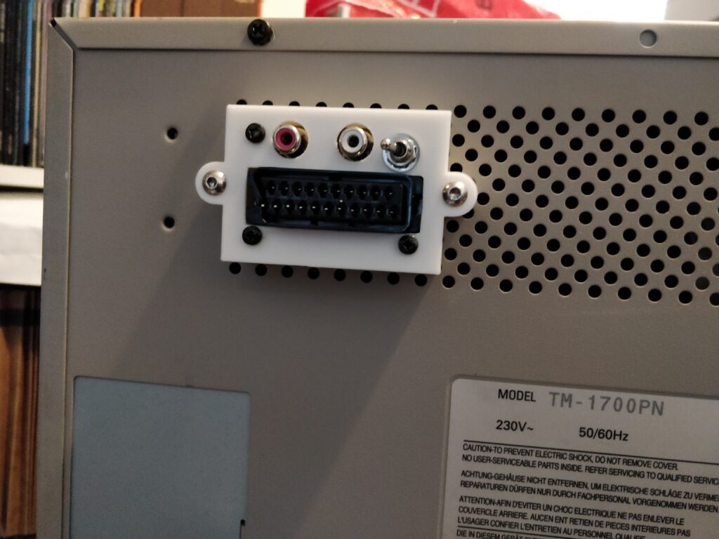
So everything is connected to the SCART breakout board I’ve designed (OSHPark) and a case that fits the grille. This monitor has a slightly different pitch of the holes, so I had to modify the case a bit. Will put the 3D model it along with the original one (70mm between holes) on Thingiverse (it’s gonna be postfixed with 72mm).

So here are the finished connections:


