Archive for April, 2021

Making a new BKM-11R cable

Tuesday, April 6th, 2021

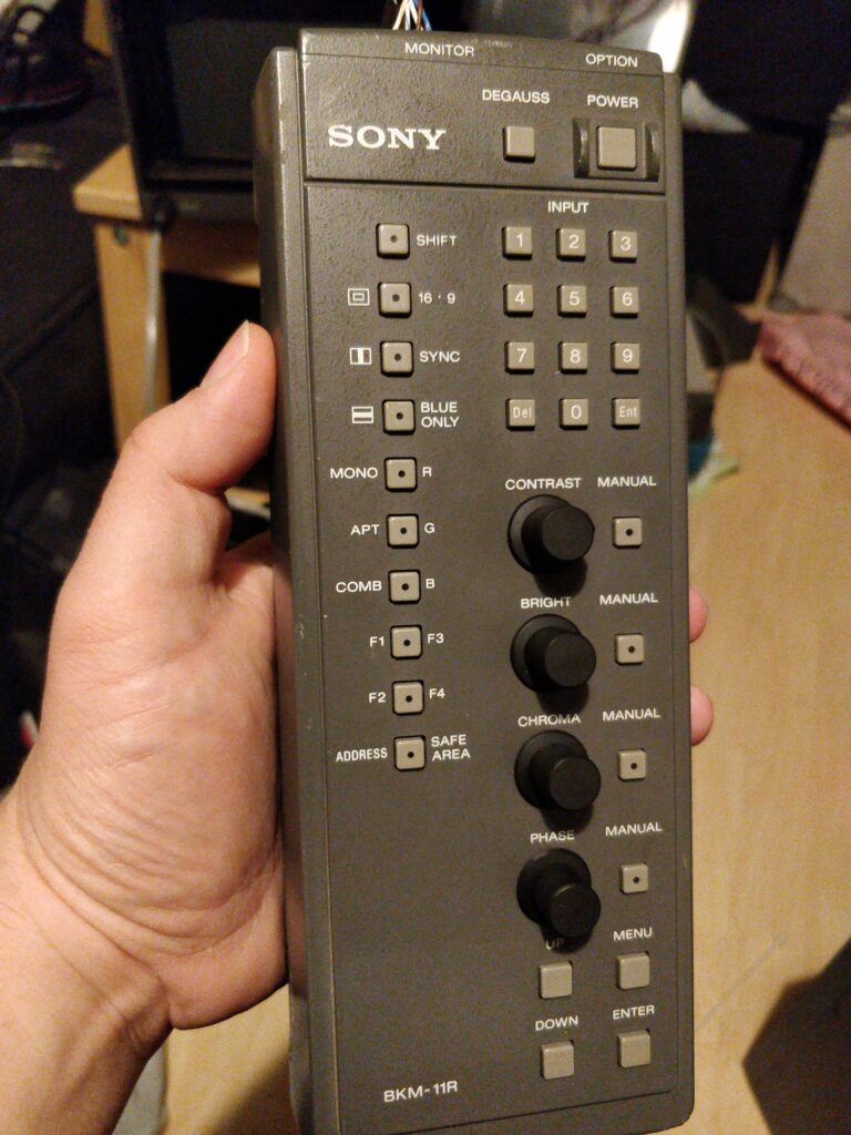
So I bought a Sony BVM-D9H1E to be able to test my BKM-129X boards at 31kHz (480p) and above. Being a *1 unit and not a *5 (like D9H5E) it has no integrated controls, and thus need an external controller. This can be either a *5 unit, a BKM-10R, or in this case the BKM-11R which connects to the front mini-DIN 8-pin option plug.

BKM-11R remote controller
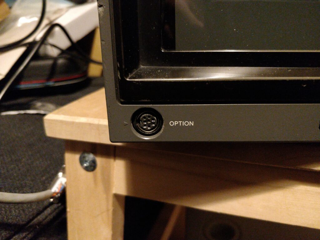
The 8-pin mini DIN “OPTION” plug of the D9H1E.

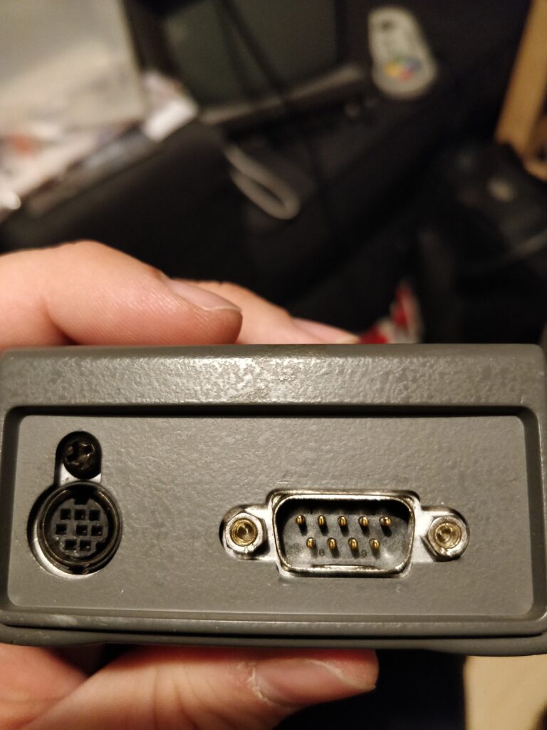
Now the controller has a DE-9 port (and another mini-DIN 8-pin plug to daisy chain further to units like the BKM-14R probe) which therefore requires an adapter cable to the mini-DIN.

The DE-9 port to the right that connects to the monitor, and the 8-pin mini-DIN to the left.

The cable didn’t come with my remote, so I needed to make a new one. Searching the internet brought me to the shmups forum where this picture exists:

The top picture is the DE-9 port of the BKM-10R and the bottom is the mini-DIN. Unfortunately the BKM-11R does *not* use the same pinout as the BKM-10R seemingly, because making a cable from the above doesn’t work. I opened up the remote and could see that ground and 5V were definitely not the same, so I started searching for answers. Although 5V and GND are easy to measure out, the TX/RX pairs are not so easy as they’re seemingly buffered by the remote for the mini-DIN port.

I was unable to find a service manual documenting the the remote, so I was kinda lost. The next step was of course to disassemble the remote further to see if I could decipher further, but then awesome guy Steve Nutter of Retro Tech (he does a lot of informative CRT related videos on YouTube, check it out if you don’t know him https://www.youtube.com/channel/UCwOTvOtoAjiqQx1PCrfmTKw) measured a working cable out, which then made it easy to make a replacement. The pinout is as follows (pin numbers are as a normal DE-9 plug):
1 – NC
2 – RXD
3 – TXD
4 – NC
5 – GND
6 – 5V
7 – ~TXD
8 – ~RXD
9 – NC

Thus to make a cable, using this pinout, along with the information fromt the shmups post by xga, the connection needs to be like this:

Signalmini-DIN (monitor)DE-9 (controller)
TXD83
5V76
RXD62
~TXD57
GND45
~RXD38
Mini-DIN female pinout (taken from Schurter 4850.2810 datasheet)

For cable, I simply used an normal unshielded Cat5E ethernet cable, and then use a twisted pair for TXD/~TXD and other pair for RXD/~RXD.

BAM! Cheap BKM-11R cable! Thanks again, Steve!
Improving 720p performance of my BKM-129X compatible designs

Sunday, April 4th, 2021

So I’ve found out I’ve made a huge mistake on my BKM-129X designs (all of them): The low pass filter of the THS7374 is *not* disabled as was intended. As I myself have no hardware to test 480p and above, so I never noticed the issue, but Bob from RetroRGB.com noticed when running 720p sources through it, there is a softness to the picture which shouldn’t be there. This is because I erroneously connected the BYPASS pin of the THS7374 to GND instead of VCC. This means that instead of disabling it, it is enforced. Nobody likes this filter, and it should never have been enabled! For 240p/480i/480p the filter makes no difference so if this is what you’re using the board for, don’t bother, but for 720p/1080i it makes a huge difference. Luckily the fix is rather easy, and can be carried out on already assembled boards.

Disconnecting BYPASS from GND

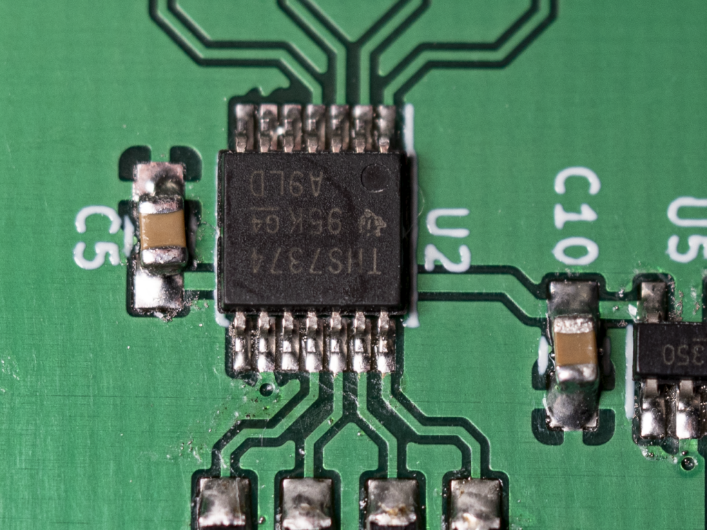
First thing to do is get the BYPASS pin (pin 9 of U2) disconnected from the GND plane.

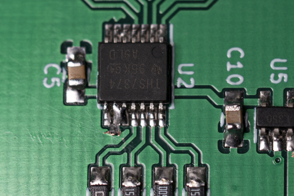
The THS7374 (U2) chip. BYPASS/Pin 9 is the bottom second pin from the left, right above the via (the black dot).
Picture courtesy of RetroRGB.com

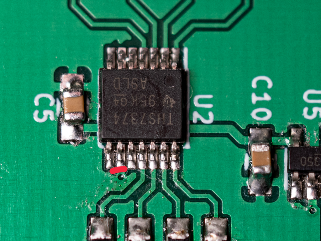
Pin 9 is connected to the GND plane through a small trace right in front of it. We need to cut this trace (or lift the pin). I prefer cutting the trace.

This small trace marked with red should be cut/removed.

Use a scalpel or boxcutter blade to gently cut it. Its not very thick but its important to ensure the connection is completely gone, and at the same time ensure the via is not destroyed. The pin to the farthest left is not connected to anything, the other is VCC. Measure that connection to GND is gone by using a multimeter set to measure resistance.

Connecting BYPASS to VCC

After severing the pin, we need to connect it to VCC to force the low pass filter off. Luckily the pin right next to it, to the right, is VCC. The easiest is simply adding a small blob of solder to the two pins.

The BYPASS pin bridged to VCC pin (pin 10).

That’s it. Enjoy 720p, and sorry for the inconvenience.