By default, the European Mega Drive (2) has a vertical refresh rate of 50 Hz, meaning the games play slower than its Japanese and American counterparts which play in 60 Hz. We don’t like that, so that needs to be fixed! So getting a Mega Drive 2 to play games in the original 60 Hz speed plus being able to switch the language on games that support it is somewhat easy, but there are some caveats, especially if you’re a purist. This guide relates to a PAL Mega Drive 2 with a VA1 board. Note that I’m still a sucker for hardwired switches, but a lot of this can also be done with a MegaDrive++ setup.
Getting 60 Hz out of the MD2
First of all, what vertical frequency the Mega Drive generates is depending on the voltage on pin 46 of the main CPU. When pin 46 is tied to 0 V/GND, it generates 50 Hz, while when it is logic high/5 V, it generates 60 Hz. On this board pin 46 is tied to GND not far from the main chip. This small bridge as can be seen below, needs to be cut.


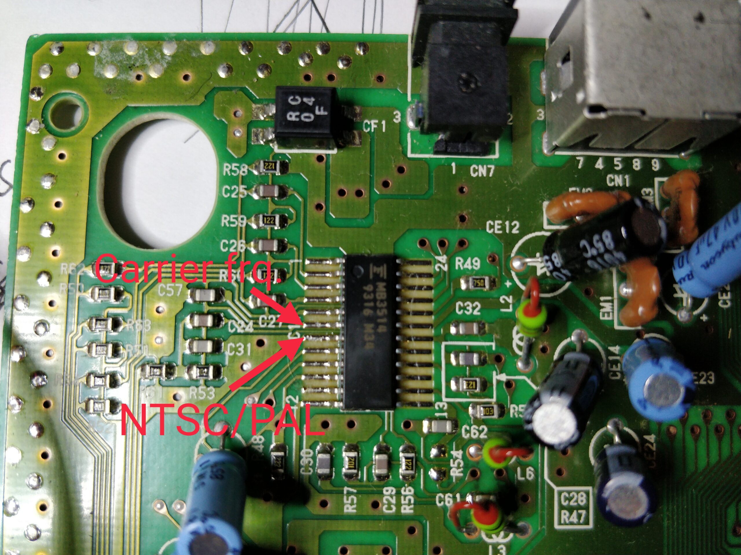
When the trace is cut like this, we isolate the pin. It is supposed to have a pull-up and if you measure between 5 V and the pin, you’ll be able to measure around 25 kOhm, so indeed it seems there is something here. At the same time, the trace is also connected to the MB3514 video encoder, which generates composite video and amplifies RGB. It is connected to pin 7 which (lucky for us) is also the pin that selects if the MB3514 should produce NTSC or PAL composite signal (and chroma in S-Video), 0 V for PAL, 5 V for NTSC. We’ll get back to this later.
Close to the power regulator (the heat sink thing) are 4 holes, which denotes two jumper points, JP3 and JP4. The left side is connected to the above trace, meaning to pin 46 and MB3514 pin 7. The right side is connected to GND for JP3 and 5V for JP4. Since the holes are through holes (most likely filled with solder) these are some good points to connect to. Now connecting 5 V to the left side will make the MD2 create 60 Hz video, and MB3514 create NTSC, while connecting 0 V will give 50 Hz video encoded to PAL. So connecting a switch here that selects between the two by connecting 0 V or 5 V from the right side makes it easy to switch between the two modes.

Now if we try to connect 5 V to one of the pads om the left side, we will see that the video is now full screen and running noticeably faster. However, if we are using composite, we might be getting a black and white image!
Dafuqs up with my black and white picture?
Usually people will attribute this to being because the TV or monitor the machine is connected to, cannot decode NTSC, and then switch to RGB. The decision is good (composite sucks), but for the wrong reasons (especially if we know the set to be NTSC compatible). So why are we seeing black and white composite video? The MB3514 is properly set to generate NTSC, however the chip also has a carrier frequency input (pin 6) which need to match the specifications the receiver expects.
For PAL this frequency is ~4.43 MHz and for NTSC it is ~3.58 MHz. Since these subcarrier frequencies are used to encode only the colors of the video signal, and we are getting black and white, something is off. If we try to measure the frequency going to pin 6 we see this when in PAL mode:

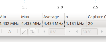
Note the Measurement in the bottom where it says “Average” and “4.434 MHz”, so here the carrier frequency is correct.
If we switch to 60 Hz / NTSC mode, we get this:
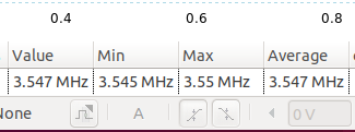
So we can see we have a carrier frequency of average 3.547 MHz, which is somewhat off the intended ~3.58 MHz, so this is why we are seeing a B/W picture; the receiver cannot lock onto the carrier frequency to decode color.
We can then deduce that the carrier frequency is created wrong, and since the frequency is created by the main CPU, the answer to why, can be found in the differences of the main oscillator which supplies the clock signal for the system. On PAL consoles this is ~53.20 MHz (which is equal to roughly 12 x 4.43 MHz), while on US and Jap consoles it’s ~53.69 MHz (which is equal to 15 x 3.58 MHz). Now what happens is, that when pin 46 is low (for 50 Hz PAL), it divides the clock by 12, and when driven high (for 60 Hz NTSC), it divides by 15 (53.20 MHz / 15 is roughly 3.55 MHz, which matches what we saw above). Now how to fix this?
Bring in the Dual Frequency Oscillator (DFO)
The Dual Frequency Oscillator is a small device based on Texas Instruments CDCE family of clock generators. It can be programmed to generate different clock signals depending on an input. A guy called micro has made a design that is a drop in replacement of the main oscillator (https://oshpark.com/profiles/micro) so building one of these, replace the original oscillator on the board, take the same signal as we send to pin 46, and insert at the DFO, we can now switch the main oscillator frequency to match the selected mode!
So we need to desolder the main oscillator and dump the DFO in. We can then take the signal to the DFO from the other unused through hole at either JP3 or JP4 and route that to S0.

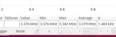
Doing this, we can then measure that the subcarrier frequency is now correct when in 60 Hz mode:

At the same time, this also fixes that the output frequency in fact was not 60 Hz, but more 59,2 MHz, which can help when connecting to some flatscreen TVs an converters like Framemeister. Note that much of this actually relates to many other 50 Hz PAL to 60 Hz NTSC conversions on Master System, PlayStation and so on.
So what about that Japanese language?
Pin 107 of the main chip selects if the machine should report as being an English machine or a Japanese machine. This “helps” some dual language games to show either Japanese or English text. An example is Quackshot. When pin 107 is connected to logic high (5 V), the machine reports English, when 0 V it reports Japanese. On this board, pin 107 is connected to 5 V through a via to a 5 V plane. This somewhat sucks, as we then either have to lift the pin, cut the trace, or cut around the via in the plane. I selected the second option: Cut the trace at the via and then scratch some of the solder mask off to be able to solder to the trace.


Bringing it all together
Now we have two places to insert information, the 50 / 60 Hz and the language. Some use two switches for this, one for each, however we can deduce that only 3 sane options exist:
50 Hz / English / Pin 46: 0 V, Pin 107: 5 V
60 Hz / Japanese / Pin 46: 5 V, Pin 107: 0 V
60 Hz / English / Pin 46: 5 V, Pin 107: 5 V
This can be done by a simple DP3T switch, so instead of having two switches, which techically gives the 4th “invalid” option of 50 Hz / Japanese, we hook up to one with 3 positions. The hookups look like this:
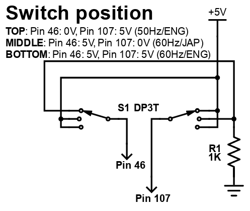
R1 is to prevent shorting the supply when switching while machine is on. It can be 1K-10K but it needs to be less than the internal pull-ups (which seems to be in the 25K range as mentioned earlier).

So I like to conceal the switch as much as possible which I do by using the left side facing the switch downwards.

Of course some mechanical holes needs to be drilled and filed in. How big this is depends on your switch.


So now, by switching we can select all three regions with correct corresponding frequencies. All good!