When applying the preempt_rt patch to the Linux kernel, EFI variables at runtime are disabled by default, seemingly due to high latencies (https://www.spinics.net/lists/linux-rt-users/msg19980.html). If you still need EFI variables accessible for userspace applications like efibootmgr, add “efi=runtime” to the kernel parameters/arguments. This will re-enable the possibility to mount efivarfs with “mount -t efivarfs none /sys/firmware/efi/efivars”. This will of course not magically make the above mentioned latencies disappear, so use this at your own discretion.
Category: Uncategorized
RGB modding JVC TM-A101G
So next in the line of small JVC monitors I’ve worked on is the JVC TM-A101G.

As the TM-1011G and DT-V100CG this is a 10″/9″V CRT pro monitor, but only has composite video inputs. I guess it’s the older version of the TM-1011G but I’m not sure, and it doesn’t matter anyways… Looking at the service manual which is available on teh webz, this uses a TB1226EN which is the same as the TM-A140PN I wrote about here, so I know this jungle a bit. I wondered if it needed I2C interception and mangling like the TM-A140PN, but already before I got my TM-A101G monitors, I helped a guy mod his, where we found out it *did* need this. Luckily the software I wrote for the TM-A140PN worked out-of-the-box here, so with that information, I started modding my own.
Opening up the monitor, the signal PCB is sorta small:

There are only two larger ICs, of which the top is the TB1226EN (IC201), which is the one we’re interested in. According to the datasheet of the TB1226EN the RGB inputs are pin 23 (R), 24 (G) and 25 (B), and according to the service manual these are “grounded” with capacitors, these being C716, C717 and C718, which can be seen roughly in the lower middle here:

So these are THT/through hole caps, which sucks, because then we need to remove the shielding that is on the other side, or disconnect the tracks, by cutting them. I chose the former. There are 4 points which needs to be desoldered for that, which requires a lot of heat because it’s connected to the GND plane, and in itself is a large GND plane. So after doing that, removing the caps with a needle-nose pliers, and either a desoldering gun, or simply by heating the solder and pulling the component, they’re quite easy to remove.

After removal, the RGB signals can then be attached to the open pads, R to the pad of C716 (the one not on GND plane), G to C717 and B to C718. The signals needs to be run through a circuit like this:
Notice the R726 just below the “VIDEO/CHROMA” text in the top right of the above picture. This is a 10K resistor, and connects to the YS pin, which is the pin needed to switch to RGB. Usually, on similar displays, there are quite low Ohmic resistors here, because it’s pulled to GND, as RGB is “disabled” anyway. To switch to RGB we need to put something higher than 0.85V at the YS pin, I usually use the 3-5V RGB blanking voltage from SCART, however if the pulldown resistor is small, it will draw a lot of current, for no reason. I therefore usually switch these pulldown resistors to 10K resistors, but here, that is then not needed. We can therefore inject RGB blanking, either from SCART or another source (a switch for example) directly at the pin, or at the side closest to the pin row of the TB1226EN (I chose this).
I inject sync directly at the BNC input of Input A to avoid sync problems, and utilize the built-in sync extraction circuitry. GND is then just whereever it’s most appropriate to obtain. Here are my connections (yellow is sync, white is blanking and black for GND):

If we don’t do anything else, the picture is really low contrast, washed out and doesn’t look any good at all. Here is where we need to mess with the I2C communication from the monitors MCU to the jungle IC. Basically the monitor doesn’t treat the jungle I2C registers correct so RGB is not properly set up, just as with the TM-A140PN. Since it was verified that the previous software I wrote for the TB1226EN works for this monitor, it was simply getting an Arduino in. Download the software here and program the Arduino with Arduino IDE (remember to install SoftI2CMaster library). I’ve begun using the Mini Pro because it’s even smaller than the Nano, with otherwise the same feature set. Mind that it should be the 5V version. So we need to isolate the jungle from the I2C bus, which is done at R291 (SCL) and R292 (SDA):

Desolder these two, and attach the Arduino here, with the wires from R291 going to A5 (SCL) and R292 going to A4 (SDA), use the pads that are “away” from the jungle. Attach the other pads from R291 to D5 and R292 to D4. If you use another Arduino than Mini Pro or Nano v3, you might need to change accordingly. Remember to solder a 2.7-4.7K resistor from D4 and D5 to VCC/5V. I do this on the back of the Arduino (which is why you can see a solder blob on VCC to the right on the Arduino, but its better to use the bottom VCC instead, as now the programming “header” sorta blocked, although not needed). Here’s a picture of the same deal:

I then use a load of hot glue to stick it to the board.


It’s important that the Arduino powers up early, to avoid the monitor not initializing, so I attach it to 9V which I found at the top of the unmounted C509 (there is 9V many places). Attach this to the “RAW” input of the Mini Pro or VIN of Nano v3. Find GND somewhere and attach to GND of Arduino.
Stereo to mono mixed audio is then routed to the audio input of Input A.

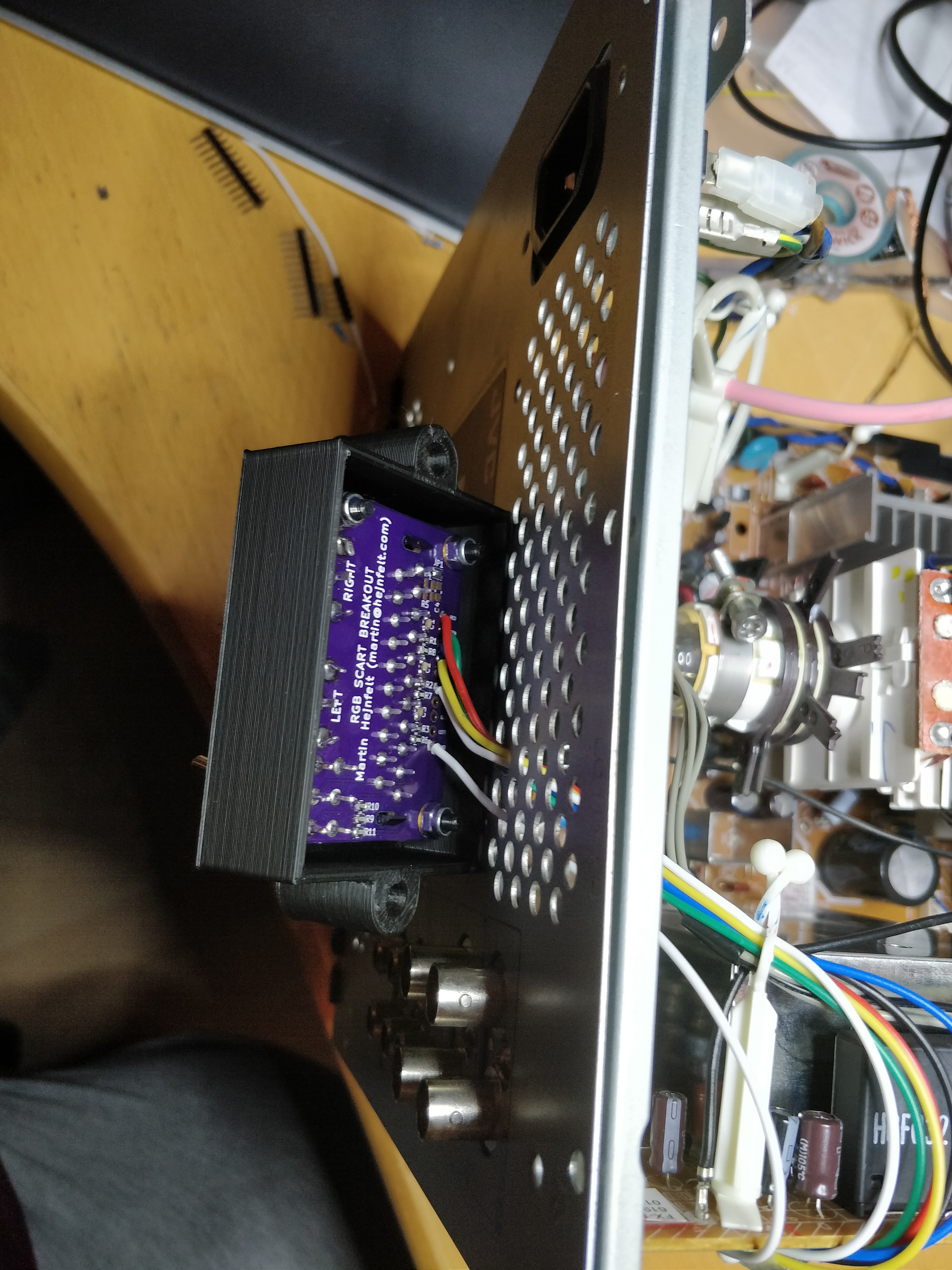
All the signals are routed to the RGB SCART breakout board I’ve made, which can be found here and a bracket that fits the ventilation grille here.

Lo and behold, RGB in all its wonders:


RGB modding a JVC TM-A170G
A friend of mine got a JVC TM-A170G which is a nice 17″ pro monitor with 750TVL. Unfortunately the monitor “only” has composite and S-Video inputs, so we talked about RGB modding it, which I took on as a task 🙂 Opening it up, it is apparent that is very close to being identical to the TM-H1750CG and its siblings.

The IC of interest is IC501, the big 56 pin IC almost at the middle, a then little to the left in the above picture. This is the jungle IC, the JVC common TA1276AN, and as always there are pin numbers marked on the boards, so it’s rather easy to find the pins we need to deal with. We need to get YS2 (pin 32) switchable to 5V, however it is pulled to GND by R554 (it sits to the right of the leg, along with C551-C553), a 0 Ohm resistor (which forces internal RGB mode, meaning deduced from composite, S-Video or YUV). So replacing this with a 10K Ohm or alike resistor makes a proper pulldown so composite is still available. The capacitors C551-C553 also needs to be removed as they are connected to the RGB pins (R/35, G/34, B/33) and would otherwise filter the video signals to GND.


Now we need to attach cables to the appropriate pads (or directly to the pins). For RGB switching, the rightmost pad of R510 (which is not mounted) is a good place to solder a wire to. The three empty pads right next to the pins are good for the RGB lines.

GND was also attached to whatever suitable point
These lines cannot be directly attached to the input connectors. They need to be attenuated, DC biased and terminated properly. Here comes the same drawing as I’ve used in most of my other posts.
I attach the RGB select/blanking pin to SCARTs blanking pin, which is 3-5V for RGB sources (pin just has to be more than 0.75V to select RGB). If SCART is not used, one could attach a switch somewhere to select it, use the voltage from the switch that selects inputs or something else.
We need to have sync getting in also. Most guides say that this should be inserted (as CSYNC) to pin 15, which is also possible, but I prefer to use one of the BNC input pins so it is properly routed (and saves some components, as we then don’t need the circuit from above on the sync line also).

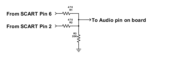
This monitor also has audio. This is injected (as mono) to input A pin. I forgot to take a picture of this, but with a multimeter, it’s easy to find the pin (it’s a bit further south of this pin, and somewhat covered by the case, but not unreachable in any way. Mono should be mixed properly from stereo if needed, this can be done with a circuit like this (if from SCART, otherwise insert left and right channels instead).

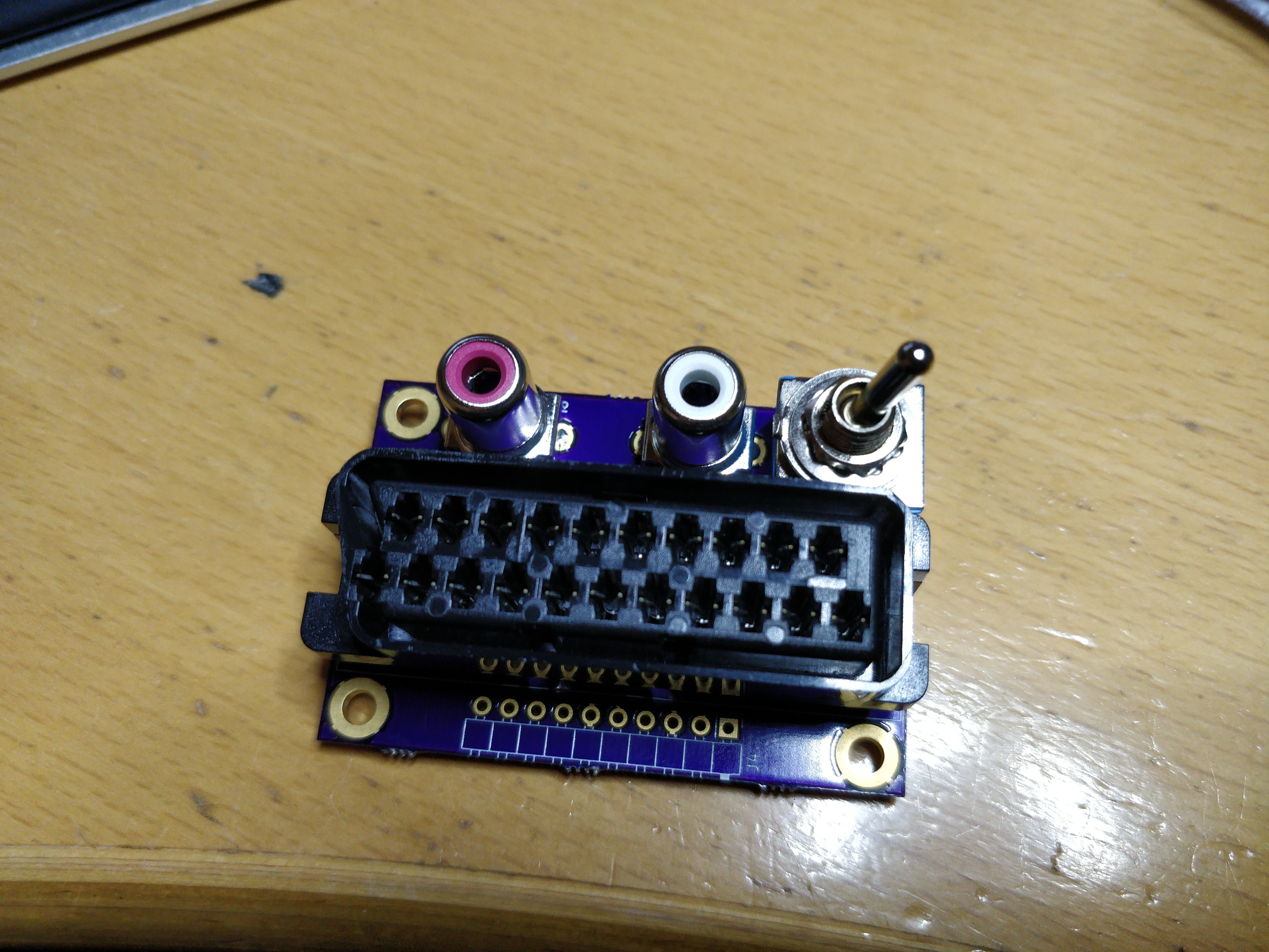
Now all the circuits can be dangling components, small boards or whatever, and you might notice no components are on the picture above. I’ve started to use a small board that breaks out SCART to the appropriate signals, AND carry the circuits for the signal attenuation (or passthrough for sync) and for stereo-to-mono. At the same time it has RCA out for audio passthrough, and a switch to select the audio coming to the monitor or to the RCAs. You can find the board here on OSHPark.
At the same time I designed a 3D printable bracket for the board which can be attaced the the monitors top ventilation without drilling. You can find the STL file and original FreeCAD files here.


And voila, RGB modded TM-A170G. Here are some pictures (taken with phone, so real life is *much* better):


RGB Modding a JVC TM-1011G
Having worked with the DT-V100CG, I stumbled upon this JVC TM-1011G that looked at lot like it, but without the option for the add-on card, thus only two composite inputs. Instead of the add-on, it had a 12V DC option installed, but also integrated audio, which I thought was cool, given I had to add this to the DT-V100CG. Now I thought the RGB mod would be similar to the DT-V100CG, and hey! It was. The board is somewhat different, but still sports the same TA1276AN jungle IC. So with the experiences from the DT-V100CG I started to RGB mod this.

First of all, I didn’t want to lose composite availability, so we need to get a pulldown resistor in between pin 32 (YS2) and GND. On both this and the DT-V100CG pin 32 is connected straight to GND, so this needs to be lifted. Unfortunately it’s connected to a bigass GND plane, so it takes some heat and patience to get up. When it is up, I inserted a 10 KOhm resistor in the original hole and tied it to the pin. Now when 5V is inserted to the pin, it changes to RGB, and when 5V is off, it’s composite.


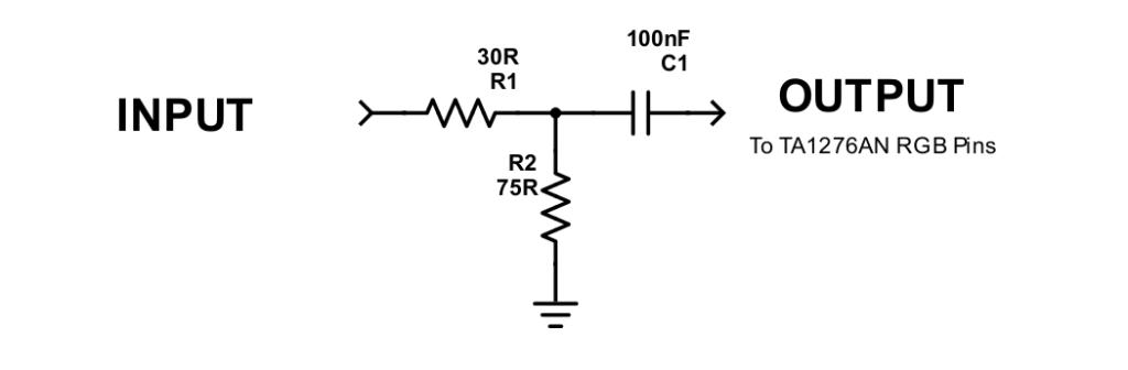
RGB lines are connected to the RGB pins (35/RED, 34/GREEN, 33/BLUE), through the “normal” circuitry consisting of an attenuating resistor and then a 75 Ohm termination, along with a 100nF capacitor for DC bias (the RGB pins have a DC offset). Some (correctly) mention the ensuring that the attenuation resistor and the termination resistor should amount to 75 Ohm, instead of adding an attenuation resistor to 75 Ohm. Sync is injected at one of the composite BNC pins, so it is routed appropriately into the jungle. Since this monitor also has (mono)audio this is injected directly at the RCA pin for the same channel as the video (I chose input A for both).
Since I’ve modded a few sets, always use SCART, instead of always hacking some wires directly on to the “naked” SCART socket, I made a small PCB to attach to. This is because the circuit mentioned above is needed, and because I also always add some RCAs and a switch to route to audio out from SCART, instead of into the often rather mediocre, at best, speakers inside these monitors, and found it easier to gather all this on a single PCB. The board has space for resistors, capacitors, the SCART, stereo-to-mono mixing circuit, and the audio switch. It then has a row of through holes to add the wires to going into the monitor. The board can be found on OSHPark here.
Now, just as with the DT-V100CG, the monitors’ software kills RGB video by completely darkening RGB registers and so on. To fix this, the I2C communication from the monitors microcontroller to the TA1276AN must be intercepted and “tampered”. I do this with an Arduino board, which in this case ended up being an Arduino Mini Pro (5V version!). Now the deal is to isolate the TA1276ANs from the monitors I2C bus, and add in the Arduino listening on the same address as the TA1276AN, instead, thus getting the Arduino to act as the TA1276AN at least to the monitor MCU. The software library SoftI2CMaster then creates a new I2C bus, which then is routed to the TA1276AN. When the Arduino gets read and write requests, it forwards those to the TA1276AN, except for the ones that kills RGB. Also it will send contrast and brightness settings to appropriate RGB registers so this can be controlled from the panels buttons.
To isolate the TA1276AN, two resistors must be removed, R6612 and R6613. They are small SMD resistors next to the TA1276AN.


The “native” hardware I2C bus (also called TWI for Two Wire Interface) on the Arduino Pro (and Nano 3.0) are on pins A4 (SDA) and A5 (SCL). We need to connect these two pins to the system, either on the pads we removed the resistors from, on the ones away from the jungle, or on any of the other ICs also connected to the same bus. I chose the latter, and connected to IC6101. Pin 9 is SDA and Pin 10 is SCL. I then create the new I2C bus on D4 (SDA) and D5 (SCL), and connect them to the TA1276AN pin 27 (SDA) and pin 28 (SCL). On the Arduino I connect two pull-up resistors of 2.7K Ohm to VCC for pullups, one on D4 and one on D5.

There’s a 100R series termination resistor into the TA1276AN on both SDA and SCL (the two resistors partly covered by the black heat shrink in the picture below). These seem not completely essential, your mileage may vary, they wont hurt 🙂
The Arduino is then glued to the PCB with hotglue. Powering the Arduino is done with by taking 12V from the PCB and connecting that to the “raw” pin. The 12V is taken from the “T” connector pin 7. If I used a 5V from another source as direct VCC, it seemed it didn’t boot fast enough, and the monitor shuts off due to not being able to communicate to what it thinks is the TA1276AN. GND is of course also connected. I simply chose the nearest easily accessible point. The software for the Arduino can be found here.

All the wires are then connected to the SCART breakout board, for which I still need to find a place for, most likely some small 3D printed bracket thing…

With all connected, presto! RGB on this nice little monitor 🙂


Update
So I finished the bracket for the SCART breakout and besides the small mess with the print in one corner, I think it turned out pretty good. Find the 3D model here.

Fixing a PSone not reading discs (bad cap)
So I have this PSone (PM-41 mainboard) that I modded with a onechip modchip and a multi frequency oscillator (I have another post on that) some time ago. It had always (at least since I got the unit) read discs rather slow, but I never thought of it, because I am not used to PSX (I generally dislike CD/DVD based consoles). Suddenly, not long ago, I couldn’t get it to read any discs. The console would recognize the disc, and go past the “menu”, but it would then sound strange, like it was retrying reads, until it would ultimately stop and hang. I tried trimming the laser pot with no real changes (except I could get it to not accepting discs at all), so I immediately blamed the laser. I then sourced another, working, PSone, and swapped the whole drive assembly, same results. I then blamed my modchip, and set the project aside. I then stumbled on a Facebook post regarding PSones not reading discs, where a guy suggested to replace capacitor C705, which is a 0.47uF/50V electrolytic SMD capacitor. Underneath it was some brown gook, that I usually find on leaked SMD caps on SNES and alike. Since I didn’t have a direct replacement cap, I found a 0.47uF/35V tantalum cap. Although voltage rating was off, I tried it anyway (I guess there would be no 50V in the PSone :P) and lo and behold, the unit now works again. It even read discs faster, I guess because re-reads are now eliminated or at least minimized.


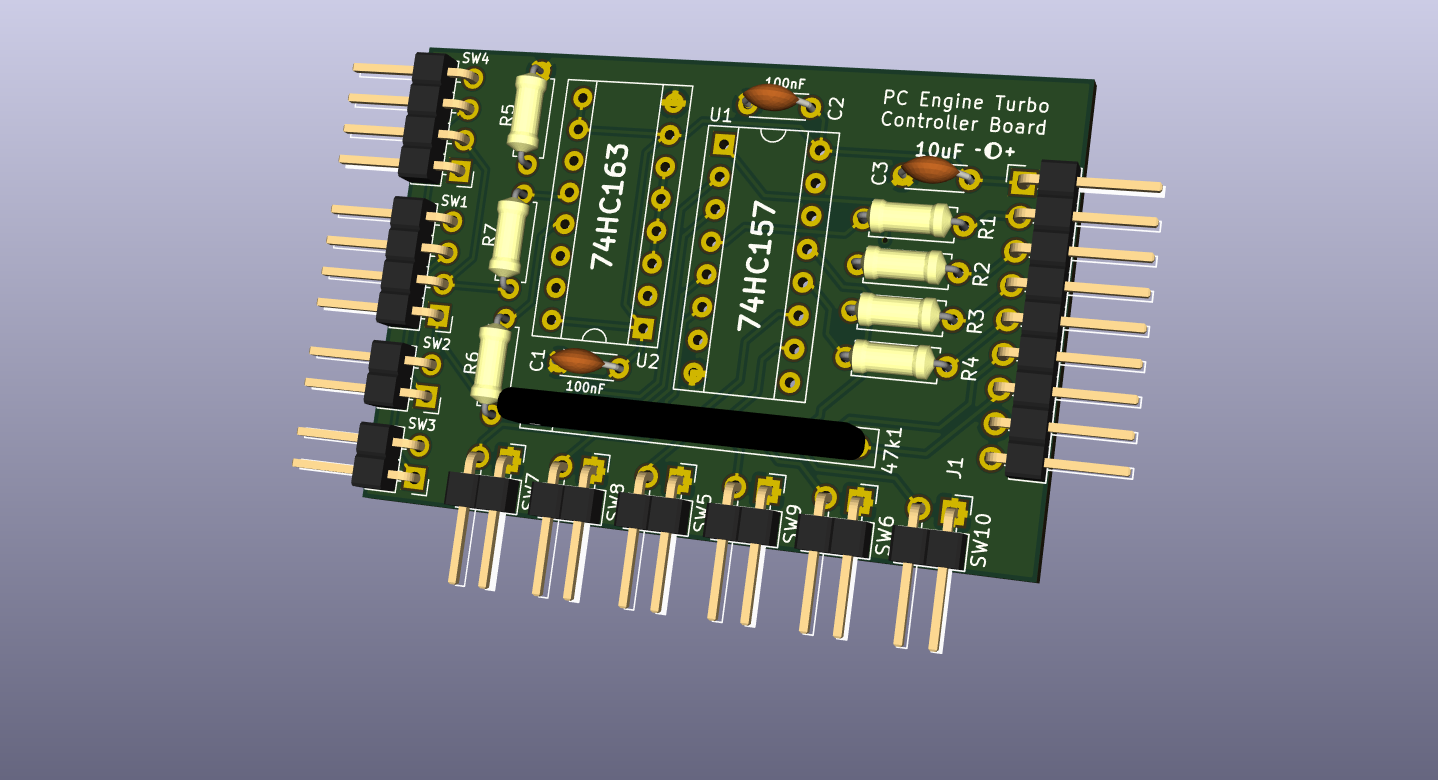
Building an arcade stick for PC Engine from scratch
So since I like my NEC PC Engine / Core Grafx, I decided I wanted an arcade stick for it. Sure I could buy one on eBay or whatever, but I wanted to check how to build one myself. Since I’m not a fan of pad hacking, where I would destroy an otherwise perfectly functioning pad (and I didn’t seem to find many cheap 3’rd party NEC pads) I looked around to find the schematics of the pad circuitry itself. Lo and behold, some italian guy has made the schematics! http://www.webalice.it/cicciopetito/ (The site seems to be down, so I’ve uploaded the schematic here, and Avenue 3 button here, 6 button here. If the author sees this and does not approve, please contact me).
So with this, I first made a crude veroboard version to see if the circuit worked (it did, here’s half a picture of it, somewhat later in the process)

So I then put it into Kicad to make a *real* PCB. This became this:

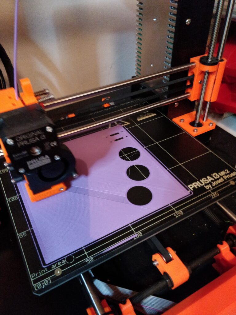
Because of my limited handcrafting skills, I decided to 3D print the whole chassis in several smaller parts (due to the build volume of my printer).
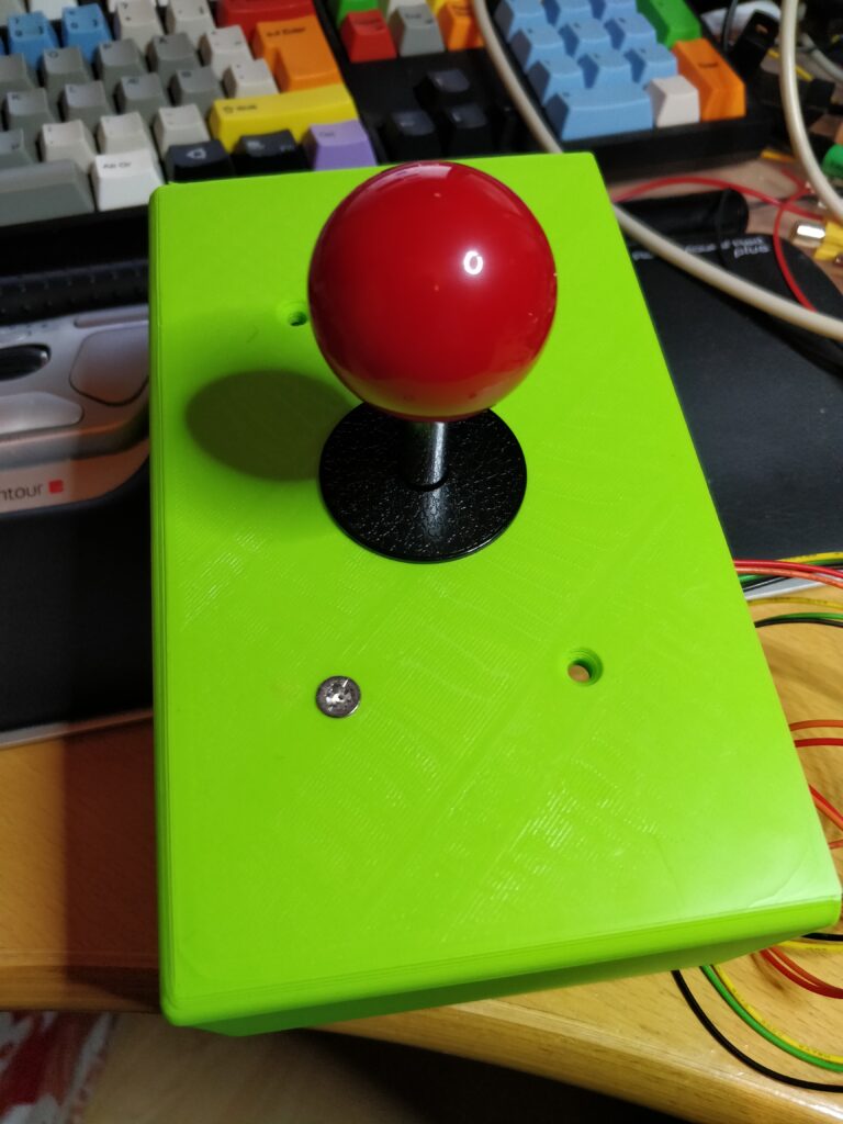

So I decided to put three buttons on top, so the red is parallel with the yellow, both acting as SELECT. Green is RUN, black is Button II, white is Button I. The two small switches are turbo for I and II.
I’ll put the project on thingverse and Github. For now the controller board is on OSH Park here: https://oshpark.com/shared_projects/8Hmi1L9I
Next job is doing the 6 button controller!
RGB modding a JVC TM-A140PN
In case you’re looking for TM-H140PN look here: https://immerhax.com/?p=558
Note: This guide works for TM-A140PN, TM-A14PN, TM-A13SU and TM-A130SU.
So, a friend of mine got a hold of some JVC TM-A140PNs (and TM-A14PN which is the same, but in plastic casing) which only takes composite and S-Video. So since nobody likes that, we wanted to RGB mod it. Open the sucker up, desolder the large metal shield in the middle of the board, and behold, a TB1226EN jungle IC. Since I now had some experience with the newer TA1276AN, I was somewhat prepared that shit might hit the fan. And of course, it did.

So blanking occurs with pin 22, Analog YS, and since I chose to blank on 5V (from SCART), we need proper pull-down, in order to avoid excessive current drain. So I switched the something like 10 Ohm resistor that pin 22 was grounded with (R726), to a 10K, so when 5V is applied, current draw is minimal, and when not, we still have 0V to allow composite/S-Video as before. After doing this, we could see that we could blank by attaching 5V to the pin and see the screen turns black. After removing C718, C717 and C716 which were the capacitors decoupling RGB pins to ground (as there is a DC offset voltage on these pins, just like the TA1276AN) and then injecting RGB to pin 23 (R), 24 (G) and 25 (B) through the same circuit as with the TA1276AN, we still got black screen when applying video.
So, with previous experience in mind (check the DT-V100CG RGB modding post), I hooked up the Arduino circuit to the I2C lines, by removing R292 and R291 and using that as entry point. R292 is the SDA line (yellow cable in the pictures), and R291 is SCL (green cable). On each line there’s also 100 Ohm resistors in-line (as in series), both on the incoming I2C and on the “new” I2C bus (they’re the resistors inside the black shrink tube). The side closest to the jungle IC was connected to the “new” I2C bus created with the SoftI2CMaster library, and the other to the hardware I2C/TWI. Firing up the screen, it didn’t boot at all. I could see it was communicating, but it never initialized properly. It seems that it is really sensitive to timing, and at the same time, the monitor software is *constantly* refreshing *every* single goddamn register in the jungle IC. So I had to rearrange the code which was somewhat trial and error, until I had something that could start.
Anyway, after doing that, I could see that the monitor software wrote 0h to register 06h, which is the RGB contrast register. Yay! Thanks for killing the RGB image! Anyway, some I2C packet mangling, and were good again. Basically, when the monitor writes to register 06h we ignore it, and when it writes to 00h we replicate that to 06h.

At the same time, I ensured that it would never mute RGB in register 1Bh, if for some reason it would think of doing that. Contrast setting on the OSD will now also work, as data is replicated to RGB contrast register. Sync was attached to line B at the board on the pin, so it is properly routed to the sync and Y pins of the jungle. Audio from SCART was merged to mono, by the below circuit and then soldered to the RCA input pin inside the monitor.
I then 3D printed a small “case” to put SCART on the back of the monitor, with RCAs to send audio out, and then a switch to switch between the RCAs and sending audio to internal mono shitty speaker.
Find the code for the Arduino here: https://github.com/skumlos/tb1226en-i2c-bridge


So there you have it!
RGB Modding a JVC DT-V100CG
TL;DR Some monitors don’t treat the registers regarding RGB picture of the TA1276AN jungle IC correct (as was the case with the JVC DT-V100CG), so when RGB modding these, the picture is dark or non-existent. I made some code for an Arduino that make it act as a bridge between the monitors MCU and the TA1276AN, for when RGB modding sets that use this jungle IC. Find code here: https://github.com/skumlos/ta1276an-i2c-bridge
Tell me more!
So I bought this small 10″ JVC monitor, that included the IF-C151HDG SDI card, and the manuals stating that an RGB card, the IF-C101CMG, should exist (no, not a IF-C01COMG, it’s not a typo). This card seems to be elusive, and I cannot find anyone who has actually seen one in real life, so I have doubts that it was ever released, also given how late in the CRT era this monitor was made.

As I use my CRTs for retro gaming, I wanted analog RGB inputs, just like on my larger JVC sets, where I also cloned the IF-C01COMG card. Anyways, I started looking at the schematics (it’s on manualslib.com) and how the IF-C151HDG worked, to get an idea of how the IF-C101CMG card might’ve been expected to work. It quickly became obvious that the DT-V100CG would never natively take RGB in, at least without modding the mainboard, as the RGB lines were unconnected (the schematics show them being coupled to GND through some capacitors, but they’re not mounted), and the pin that selects RGB on the jungle IC, YS2/pin 32, was directly tied to GND. The IF-C151HDG card converts the SDI signal to RGB, which is then “transcoded” to YPbPr through an analog circuit, which is then thrown into the jungle IC. Since the jungle IC converts back to RGB for the CRT, I started to feel this was a long way for an analog signal to run.
Anyways, the monitor uses the quite common (at least for JVC sets) Toshiba TA1276AN jungle IC, and many guides exist for RGB modding sets that use the same jungle, so I thought that that was the way to go. Looking at the schematics and PCB layouts, it seemed that I first needed to release the YS2 from GND to be able to control RGB. After severing the trace around the pad, I could measure that it was *still* connected to GND.

Looking closer at the PCB, I could now see that there were more than 2 layers of copper, but the other layers aren’t shown on the layout in the service manual, so the pin was most likely attached to GND also on a deeper layer. So the only thing left, was to lift the pin. So I did that, and attached the pin to a DPDT switch, that switched between 0V and 5V. According to the datasheet of the TA1276AN when YS2 is above 0.75V it switches to the RGB lines. You can find 5V on pin 15, at least on the DT-V100CG.
After attaching the switch, I tested that I could activate the RGB pins by connecting a composite video signal to one of the input ports, and then flip the switch to see the image become black (because I hadn’t attached RGB yet).


The RGB video signal should then be connected, which are pin 35/red, pin 34/green and pin 33/blue. Sync goes to Y1/pin 15, but instead of wiring to that pin, I simply wired to one of the composite inputs, as they also end up being routed to Y1.

Now the RGB lines are shown to be 0.5 Vpp levels in the datasheet, which is a tad lower than the usual 0.7 Vpp. As it is desired to terminate the signals with 75 Ohm resistors to keep signal integrity, attenuating the signal to 0.5 Vpp requires a resistor around 30 Ohm in series with the signal. The 30 Ohm resistor is somewhat optional, since the jungle IC does accept the 0.7 Vpp signal, however this might cause a too bright image. I actually decided to put 15 Ohm in 😛
So after making this, I attached a SCART plug, and fired everything up, aaaaaand black screen… Nothing was coming through. Now I had just heard a similar story from another user modding a JVC monitor with the same jungle IC, so I got curious. The other user had gotten a faint image, by removing all the resistors (the caps are necessary as the TA1276AN has a DC offset on the inputs) so I tried the same, and voila, there was a faint image, unusable, but still there. So the signal *was* coming through the chip, but it was *really* dark. OK, so I tried measuring it all through, to see if there was some short circuits or whatever to ground, I measured with an oscilloscope that the signal levels coming in were the right voltage, and so on and so on, but all was good.
I noticed that the brightness and other settings I could tamper with through the OSD, did absolutely nothing to the image. I then started to read the datasheet of the TA1276AN more thoroughly, to understand how this worked, and found out that all these settings, brightness and so on, are controlled by the monitors microcontroller (MCU) through an I2C line. I then saw that there were separate registers for brightness and contrast, depending on if it was external RGB (pin 33/34/35), or the internal signal generated by the chip itself from the composite video, S-Video or YPbPr. I then attached a logic analyzer to the I2C line and could see that brightness and so on wasn’t written to the RGB registers. But the two registers should be predefined to 80h, so unless the MCU actually reset them, they should still be good (except the most significant bit of the RGB contrast register, HI BRT, more on that later).
There is a lot of communication with different chips on the line, so I decided to sniff what was coming to this exact chip only, so I wrote a small program on an Arduino that acted as a I2C slave on the same address as the TA1276AN, that would write the data it received out to the serial debug. The I2C address of the TA1276AN is 44h, although stated as 88h in the datasheet, but this is because the datasheet specifies the address along with the I2C read/write bit, which is the least significant bit in the address byte. When writing, this bit is 0, so 44h shifted one bit left plus 0, is 88h. For the same reason they specify that the read address is 89h, because when reading, the least significant bit is 1, so 44h shifted one bit left is 88h plus 1, 89h. Anyways, since having two units with the same address on an I2C line is bad, because they’ll both acknowledge the data, I inserted a buffer between the Arduino and the I2C line (made by serial coupling two 74HCT04 inverting buffers per line), so the ack from my Arduino would go unnoticed. I could then read all data coming to the jungle IC, and noticed that register 05h (RGB brightness) and 06h (RGB contrast), were forcibly set to 0 by the system! Fuck a duck!
So to remedy this, there is only one solution (as rewriting the software for the MCU seemed a bit far reached), namely to intercept and tamper with the I2C communication. So I continued my Arduino program, and wrote a program that by using a secondary bit-banging I2C master, could act as a bridge between the monitors’ system and the TA1276AN, but where I could control what was being written, and to which register it would be written. At the same time the program had to deal with the constant status readouts the monitor does, because if something goes wrong, and something doesn’t respond, the monitor shuts off. The program now copies brightness and contrast writes to the RGB registers also, so the OSD actually also function on the RGB line. At the same time, it clears the HI BRT bit (High Brightness Colors) of the RGB contrast register, which apparently make the picture quite dull if enabled (maybe its because it expects the input to have high brightness colors, which it then attenuates a bit) which it is by default. The code was tested on an Arduino ATmega2560 clone, which is rather bulky, but I haven’t gotten the smaller Nano V3 yet, that should be possible to simply integrate somewhere inside the chassis.

I will update when I get the Nano, because the code most likely needs some tweaking also. You can find the code here: https://github.com/skumlos/ta1276an-i2c-bridge
To insert the bridge, it is needed to isolate the TA1276AN without disconnecting the other I2C units. On the DT-V100CG there are two 100 Ohm resistors (R6612 and R6613, you can see them to the left of the TA1276AN on the opposite side of the lifted pin 32) going to the I2C pins, which I desoldered, and then attached the Arduino to the bus, by using the pins on another I2C device (which was on the same bus, note that there are/could be multiple I2C busses) and then attached the “local” I2C bus from the Arduino to the TA1276AN. Since I2C requires pull-up resistors, and the internal pull-ups on the ATmega apparently can make the I2C bus slow, I decided to use some 2.7K external pull-ups connected like this:
So I fired everything up, aaaand presto! Pristine RGB image! Note that this monitor has quite low TVL, and all images are shot with a phone. None give it proper credit.


I now need to tidy everything up, get the Nano in, to contain everything inside the chassis. Although this was made for the DT-V100CG, any monitor that uses TA1276AN, but isn’t RGB aware, should be able to use this.
Update
After getting the Arduino Nano clones, I basically just needed to find new ports for the secondary I2C bus, and that was it. I soldered the pullups directly to the board, and mounted it in the bottom.


The Arduino is powered from CN6001, where pin 15 is 9V and pin 14 is GND. Pin 15 is then connected to the “RAW” pin of the Arduino, so it uses the onboard 5V regulator for the ATMega328P MCU. GND of the Arduino is then of course connected to pin 14, GND of CN6001.

I decided to use SCART and thus also have 5V blanking, so the blanking pin from the jungle was pulled low by a 51K resistor, and then the blanking attached to pin 16 on the SCART plug. I pulled all cables out the back and 3D printed a bracket to attach it all to, including 2 RCA for the audio out. At the same time I am going to build a small speaker (magnetically shielded) to allow for sound. That’s what the switch is for, select internal sound or pass to speaker.

The speaker is going to sit in the corner, dunno how it’s gonna sound, as I haven’t received it yet. 3D files here: https://www.thingiverse.com/thing:3441538
Update 2: The speaker sounds fine. A bit tinny of course, but I put some speaker dampening material whatever its called, white wooly stuff, inside the orange case, which improved a lot. I used a PAM8403 class D amplifier thingy from eBay to drive it, works a charm.
Enjoy!
Converting a T64 file to D64 in Linux (Ubuntu)
So I had a lot of Commodore 64 games saved as T64 “images” which is very space conserving. I however had to use these on a SD2IEC which does not support T64, so the obvious choice was to convert them to D64, although it takes more space (as each D64 is a disk image, whatever remaining space there will be, will be “slack” space). Anyways, who cares about space in the age of 100’s of GB SD cards costing $20. The “best” option I guess would be to directly extract the PRGs but I haven’t gotten to that, and this page is more or less a reminder to myself… Anyways, I started to go through the internet to find a quick solution to convert all these games, and I found a lot of different options, mainly Windows stuff that would need to run in wine and most likely be non-scriptable to extract. Some mentioned c1541 which is a part of the VICE project, which is included in many Linux distros. As I use Ubuntu, this was also the case, so apt-get install vice, and it’s in. c1541 starts a “shell” to take commands in, but they can also be given directly from the command line. So without further ado, the one-liner that converts a .T64 file to a .D64 is:
c1541 -format <DISKLABEL>,00 d64 <DSTFILENAME>.D64 8 -tape <SRCFILENAME>.T64
<DISKLABEL> should be replaced with the desired label name of the disk.
<DSTFILENAME> is the D64 filename (without the .D64 suffix).
<SRCFILENAME> is the source filename of the T64 (without the .T64 suffix).
Example (for Blue Max):
c1541 -format BLUEMAX,00 d64 BLUEMAX.D64 8 -tape BLUEMAX1.T64
This yields:
Unit: 0
Formatting in unit 8...
Writing `blue max+' ($0801 - $5618) to drive 8.
Writing `blue max spic' ($0801 - $1A1A) to drive 8.
Writing `blue max+ crazy' ($0801 - $6324) to drive 8.

3 files copied.
And we’re good! Gonna look into the direct to PRG stuff….
Fixing Samsung 2493HM not turning screen on, blue LED blinking
So I have a somewhat old Samsung 2493HM LCD monitor, which stopped turning on. The blue indicator LED would start blinking really short with a 1 second interval or so, but not turn solid on, and screen show an image. Sometimes if it stood blinking, it would suddenly turn on and screen would work fine, until powered off, and it would do the same again. This in my head sounded like a bad capacitor, so I disassembled the screen to investigate.
This is quite easy: Remove the 4 screws in the back on the bottom.

Then there’s a small notch in the bottom where you can insert something flat, and then simply pull the back cover off, use some force, it’ll be fine (hopefully).

Disconnect the CCFL headers to the left by pushing the gray small connectors’ tabs and pull backwards.
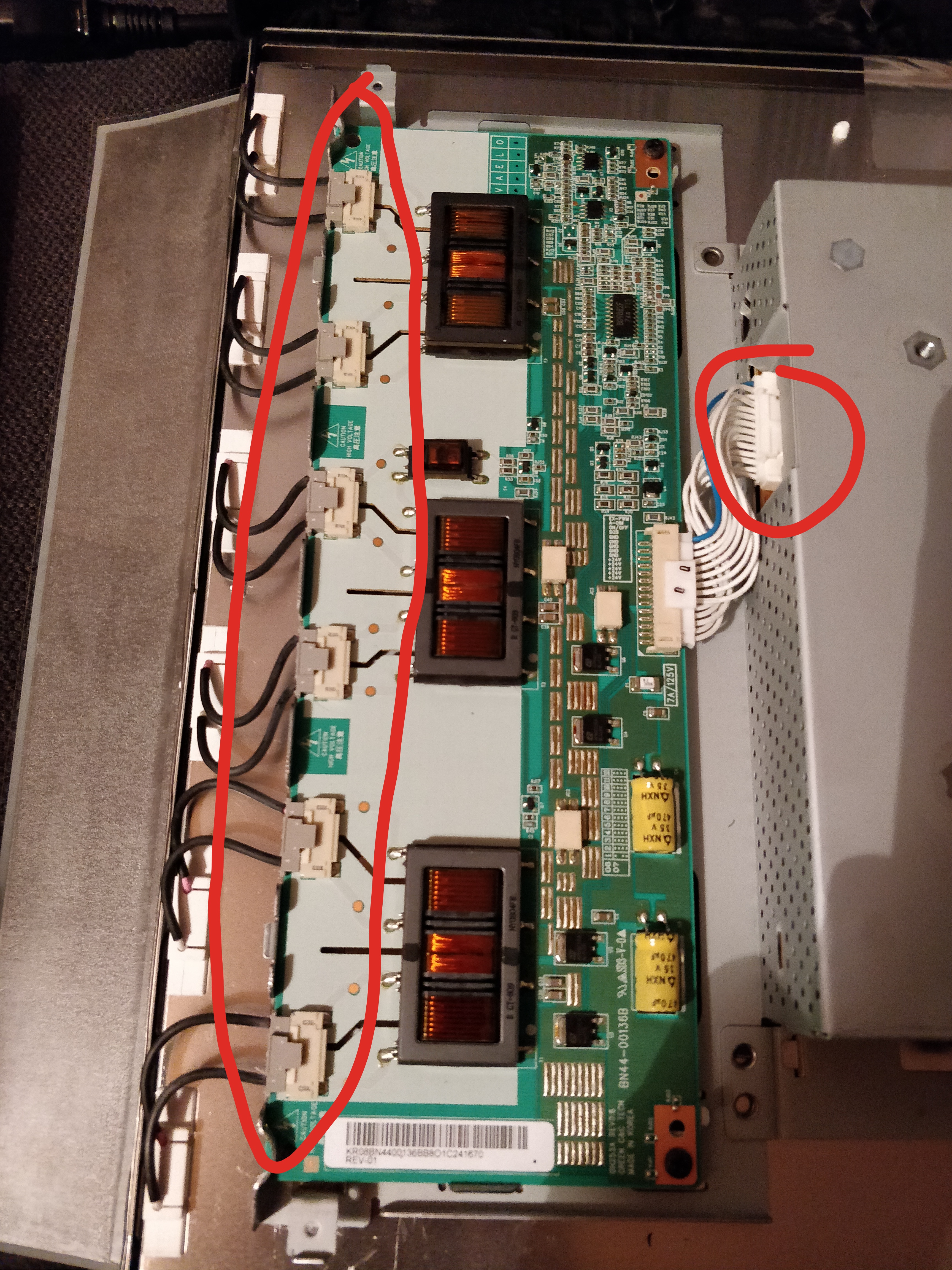
Remember! This is CCFL, so high voltage shit! Disconnect the power connector to the CCFL voltage board at the metal housing to the left.
Then the two cables at the lower right. Note the one I’ve marked here is quite fragile, I broke one of the wires, so the front buttons didn’t work until I rewired it.

Turn the whole block upwards. Theres a LVDS cable going from the A/D controller board to the right, disconnect that either by the screen or by the board. You can now move the whole block freely.
I didn’t take pictures of this, apparently, but most likely you can find a disassembly guide otherwise.
The power board has 4 screws, remove those, and the pull the ESD/grounding tape at the top to be able to remove the board. Note, again there are some high voltage capacitors here, especially a 450V/82uF sucker. Now inspecting the capacitors I found that this 2200uF/10V electrolytical capacitor (marked in red) had bulged and also it looks like it has leaked in the top.


Anyways, I replaced this with a new, and presto, screen works a charm again 🙂