RGB A/V Amp for PCEngine and friends

September 26th, 2018

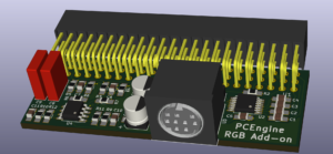
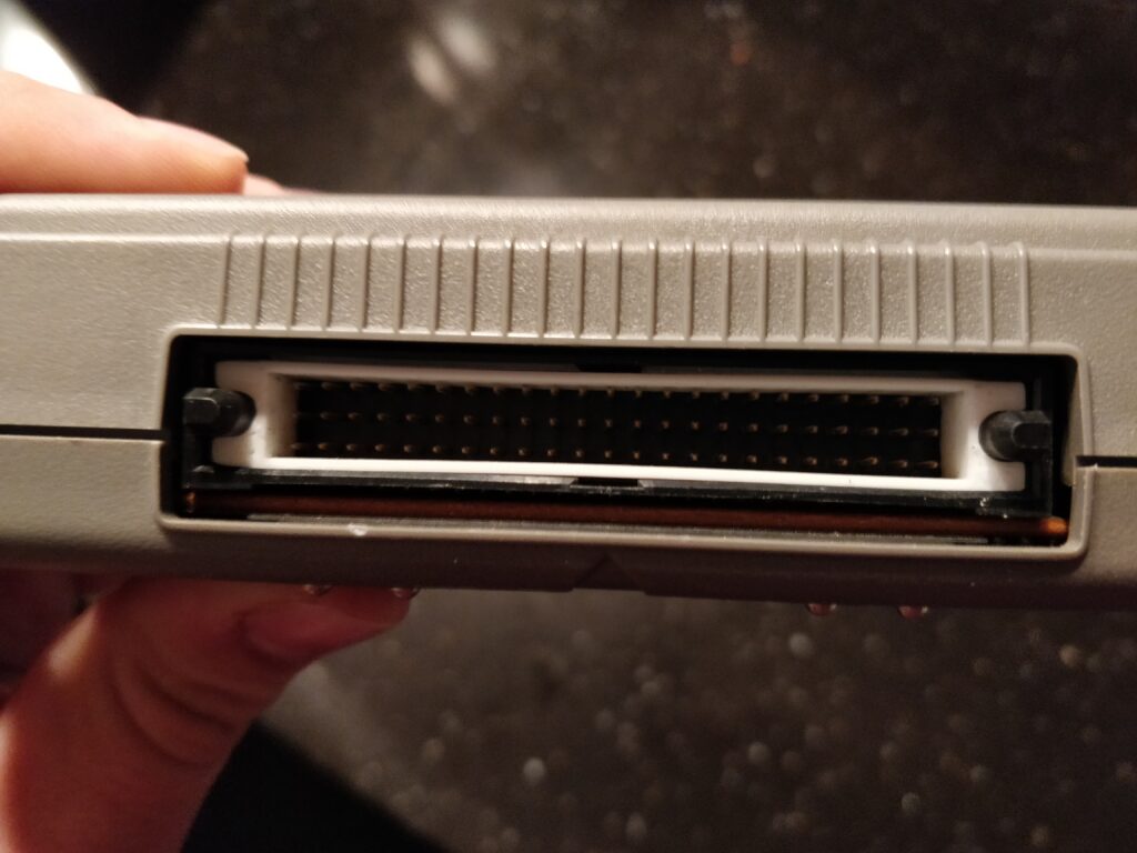
So I bought a Core Grafx machine, and it’s really nice. It has composite output which is of course better than the RF-only white PC-Engine, however they all have that big expansion port on the back, which has both audio AND RGB signals in it, so somehow getting that turned into a SCART plug seemed a no-brainer. There are many boards on eBay and the likes, that do something with this port, giving composite video, giving RGB and so on, in different packages. Most of them are quite big, expensive and/or complex. I thought it would make sense to try to make a simplified version that was as small as possible, so I came up with this:

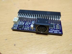
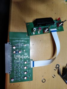
This is a 3D render of KiCad project. It is based on the popular THS7374 4-channel video amp, which amplifies RGB and composite, while sync goes through a 75Ohm resistor. The audio which is rather low, is amplified by a TS922A opamp. All this is then collected in a SEGA MegaDrive/Genesis 2 compatible 9-pin Mini-DIN plug, for which RGB SCART cables can be bought cheap on eBay. The cable should contain at least some 75Ohm resistors on the video lines (which the cables *should* have as the MD2/Genesis2 requires it) and 220uF or higher caps are also recommended, again they should be there. There’s a jumper behind the DIN plug to enable the filters of the THS7374, for a softer image if that is preferred. The large 69 pin plug is a Samtec SSQ-123-02-T-T-RA connector (which is quite hard to come by) and that can be substituted for whatever 2.54mm pitch 3-row female socket you can find, its only the left 6 pins (2×3) and right 9 pins that are used, rest are all kinds of unused stuff for this. The finished assembled unit looks like this:

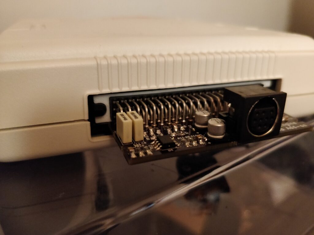
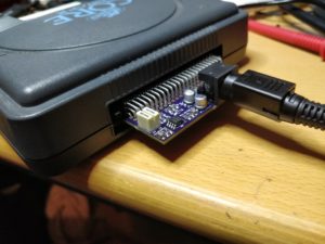
And attached to the Core Grafx:

Here’s some pics of the unit attached to a JVC TM-H1950CG, but to be honest, my shitty phone camera does not do it justice, the colors are *really* nice, really much more vibrant than this shows…

Board with parts list here on OSH Park.

KiCAD project here.

Update

Since the board just sits by the pins, it is rather poorly mechanically attached. I therefore designed this small 3D printable bracket to insert into the PC Engine expansion port to relieve the mechanical strain on the unit, and secure the PCB better.

The bracket inserted
Bracket and board

Download 3D files here (Thingiverse)

Cloning the JVC IF-C01COMG card, Through-hole version!

July 5th, 2018

Update: Find a full-sized version here: https://immerhax.com/?p=533

So, after I posted the previous board around the internet, some people were “frightened” by the small SMD components as it takes some skill and also some more precise soldering irons to deal with these. I thus decided to make a through-hole version which is much easier to solder by hand. OSHPark page here: https://www.oshpark.com/shared_projects/NHivAGjf

Compatible with the same input boards as the SMD version. Enjoy!

KiCad project here: https://github.com/skumlos/if-c01comg-clone-tht

Cloning the JVC IF-C01COMG card

May 2nd, 2018

Update: Find a full-size THT version here: https://immerhax.com/?p=533

Update: Through hole (THT) version here.

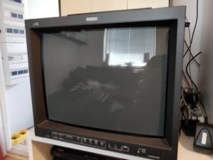
So I bought a couple of the JVC TM-H1950CG monitors, and they are crazy awesome, BUT only have composite and S-Video inputs by default.

As I was going to use these monitors for retro gaming I really wanted RGB(S) input and preferably with SCART.

I saw in the manual that a card existed to supply RGB input through BNC, the IF-C01COMG card. This card is rather rare and cost a fortune.
So while I searched for it, I found people RGB modding the monitor directly, by inputting the RGB signal directly to the “jungle” IC, which of course would work, however interfacing directly to the IC like this, seemed a bad idea ESD wise and so on.
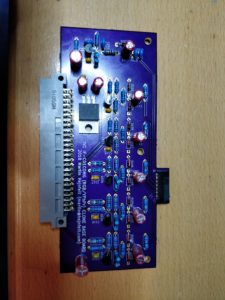
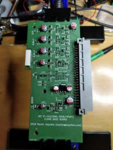
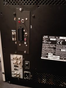
So searching on, I stumbled upon this. This guy had looked into the original card and found that it was quite simple, and basically is some input protection, signal conditioning and so on, with rather simple components (roughly some transistors, resistors and capacitors). He (and many others I’ve found out) has built the circuit onto perf-board with excellent results. I prefer “real” PCBs so I put it all into KiCad (so awesome application) and made a PCB for it. The result is this.

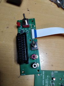
Since I prefer SCART, and others might prefer BNC, some RCA, I thought that instead of making different boards, I would design it as a base board with the actual functionality of IF-C01COMG, but with the input connectors moved to a separate “daughter” board. This would also save PCB space which is expensive. I decided to use SMD components to save space, but decided on 0805 size as they’re possible to solder with “normal” equipment.
The SCART input board can be found here.


In order to fix the input board to the chassis, I designed a bracket to hold the SCART board, which can be 3D printed. The bracket can be found here.

I also have an untested BNC input board, check it out here.

KiCad project here: https://github.com/skumlos/if-c01comg-clone

So if you’re having trouble getting the real deal, here’s an option to fix your JVC monitor up with *real* RGB 🙂

IKEA Dalskär aerator

February 6th, 2017

Having a lot of IKEA gear at the house including faucets, I had to replace an aerator on a Dalskär faucet because it was limestoned to hell. It had a coin slot, which was meant as the way to remove it, but due to the amount of limestone, it broke to shits. Anyways, it seems to have some sizing that is rarely used (M18.5x1mm threading), and looking on the internet I found out its made by a company called Neoperl, and its called Caché TJ PCA. I found a replacement unit numbered 636165 (Identnummer) with the text “Caché-HC-TJ-male M18.5×1 B” and “Z.636.165” also, barcode 7612158414436. It seems to come from Germany. Anyways it fits the Dalskär unit, and without having tried, it also seems to work with the IKEA Ringskär faucet.

OpenVPN with Yubikey 4 and PIN code

January 19th, 2017

After buying a Yubikey 4, I wanted to see what this little sucker could do, besides being used as U2F two-factor thingy for Gmail and so on, so I found out it could be used as a smartcard, meaning I could save X.509/PEM keys and certificates inside it, which I again could use for my OpenVPN connections! Happiness was in my face, until I found out that OpenVPN and PKCS11 with PIN codes is currently somewhat broken on some systems (including my Ubuntu 16.04), as I need to enter the PIN via the OpenVPN Management interface due to some broken systemd-ask-password thing. This severely complicates my setup, as I usually just start the OpenVPN connection via the terminal by something like “sudo openvpn <configfile>” which was suddenly not possible, or at least I then needed to do a lot more… So after thinking (whoa) and googling some, I came up with this small bash script utilizing netcat and some piping to automate this whole shebang. The script requires that the OpenVPN client configuration has these lines:

auth-retry nointeract
management 127.0.0.1 8888
management-query-passwords

So we start a management interface locally on port 8888 and query passwords here. The script then looks like this:

#!/bin/bash

USER=`whoami`
MGM_PORT=8888

if [ "$USER" != 'root' ]; then
    echo "Must be run with superuser priviledges"
fi

if [ -z $1 ]; then
    echo "Usage: $0 < vpn-config >"
    exit 1
fi

printf "OpenVPN PKCS11 PIN wrapper\n"

read -s -p "Enter PIN: " PINCODE

printf "\nStarting OpenVPN\n"

/usr/sbin/openvpn $1 > /dev/null &

OPENVPN_PID=$!

# Give OpenVPN a chance to get somewhere 
sleep 2

PIPE=/tmp/ovpn_pkcs11_fifo

trap "rm -f $PIPE" EXIT

if [[ ! -p $PIPE ]]; then
   mkfifo $PIPE
fi

# Start nc with a 2 second delay
(sleep 2 && nc localhost $MGM_PORT) > $PIPE &

SUBSTRING=

while true
do
   if read LINE < $PIPE; then
      if [[ $LINE == *"PASSWORD"* ]]; then
         SUBSTRING=$(echo $LINE | cut -d "'" -f 2)
         break
      fi
   fi
done

echo "password '$SUBSTRING' '$PINCODE'" | nc localhost $MGM_PORT > /dev/null

printf "Write 'quit' to kill OpenVPN instance: "

while read LINE; do
   if [ "$LINE" == "quit" ]; then
      kill $OPENVPN_PID
      exit 0
   fi
done

Creating an 8-port ethernet based power switch

April 10th, 2016

Since I have 8 old retro consoles/computers connected to a TV, I decided that I needed to be able to switch these on and off individually, as some console PSU’s influenced others, creating interference on the video output. Another reason was that I really did not want all these old PSUs connected all the time (who knows when these old electronics are going to burn up). So to solve it, I needed some relays capable of switching 230 VAC (this is Europe :P) and something to control them. I really wanted it to be ethernet based, in order to be able to switch them from my phone or any other external device, without hard-wiring controls directly to the power switch.

There is nothing new to this system, many others have done the same 🙂 This is just my implementation…

Anyway, to do all this, I chose a 8 port relay board similar (maybe the same?) to this:

8-Channel 5V Relay Module

Instead of using an Arduino or whatnot, I chose the Raspberry Pi. Mainly because I had one lying around, and because I’m familiar with it. The one I used was the ooooooold 256MB B version (first released version) and an installation of minibian (https://minibianpi.wordpress.com/) on a 1GB SD card.

Although the relay board is 5V, and the GPIO of the Raspberry Pi is 3.3V, as the inputs are active low, the 3.3V is apparently enough to keep the relay from switching. Thus we need no fancy interface voltage converting boards or whatever.

Anyway, the biggest hurdle to this whole system, is that the Raspberry Pi kernel defaults most GPIO to inputs and with an active pull-down. This sucked bad, as the system is in a rather “unstable” state until the linux system has booted and my application can “fix” the GPIO direction, causing some rather unfortunate switching of the relays on each boot, which kinda sucks when dealing with “high” voltage like 230 VAC.

But as always, this can be dealt with, and rather elegantly, by using device tree. Seems that the Pi reads a file called dt-blob.bin located on the “/boot” partition of the SD card, IF IT IS THERE (which it is not by default). However, this file can be created (yay) and changed so we can deal with HOW the default pins are set, to accomodate to my usage here. Long story short, I downloaded the dt-blob.dts file from the Raspberry Pi repo

wget https://www.raspberrypi.org/documentation/configuration/images/dt-blob.dts

and added these lines to the section representing my Pi (being the first):

 pin@p1 { function = "output"; polarity = "active_low"; startup_state = "inactive"; termination = "pull_up"; };
 pin@p4 { function = "output"; polarity = "active_low"; startup_state = "inactive"; termination = "pull_up"; };
 pin@p17 { function = "output"; polarity = "active_low"; startup_state = "inactive"; termination = "pull_up"; };
 pin@p21 { function = "output"; polarity = "active_low"; startup_state = "inactive"; termination = "pull_up"; };
 pin@p22 { function = "output"; polarity = "active_low"; startup_state = "inactive"; termination = "pull_up"; };
 pin@p10 { function = "output"; polarity = "active_low"; startup_state = "inactive"; termination = "pull_up"; };
 pin@p9 { function = "output"; polarity = "active_low"; startup_state = "inactive"; termination = "pull_up"; };
 pin@p11 { function = "output"; polarity = "active_low"; startup_state = "inactive"; termination = "pull_up"; };

and recompiled to dt-blob.bin (as per https://www.raspberrypi.org/documentation/configuration/pin-configuration.md)

When this is working, the relays are all off (because of our pull-up) on boot.

Next thing was writing a small application to deal with the I/Os via ethernet. Long story short, I used the WiringPi library, and made a small server that accepts JSON encoded packets to get and set the I/Os. Get the awesome code here: https://github.com/skumlos/relayserver

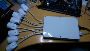
I wired up 8 230 VAC sockets to the relays, put in a hard switch to be able to “really” kill the outputs if needed, a IRM-10-5 PSU from Meanwell to drive the Pi and a chassis RJ45 plug for the networking. All in all it looks like this:

retropower

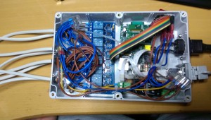
And like this on the inside

retropower-inside

Getting the Adafruit PiTFT 2.8″ with capacitive touchscreen working on Hummingboard i2ex

August 17th, 2015

To get the PiTFT 2.8″ with capacitive touch up and running on the Hummingboard i2ex, a few steps are needed. I am using the Debian Wheezy image from Igor Pecovnik (http://www.igorpecovnik.com/2014/08/19/cubox-i-hummingboard-debian-sd-image/) as it includes fbtft support and everything else (almost).

Igor already explains 49% of the setup to get the unit working, as he has a small guide to setup a 2.2″ Adafruit screen on the Hummingboard. However the 2.8″ version I have, comes assembled with a pin row to fit directly on the Raspberry Pi pin header, so to fit it onto the pin header of the Hummingboard we need to tweak the IO’s used to get some picture up.

Igor writes some info here http://www.igorpecovnik.com/2014/08/19/cubox-i-hummingboard-debian-sd-image/#display which we can (almost) use out of the box. Difference is that the 2.8″ has no RESET pin (and the LED which I guess is backlight is not connected by default, I’ll look into that later) and the DC pin is on another pin. To get it working we change the line to this:

fbtft_device name=adafruit22a rotate=90 speed=48000000 fps=50 gpios=dc:67 busnum=1

And insert it into /etc/modules. It will now be seen as /dev/fb2 and can be used with utilities like fbi. To get a console up, edit /boot/boot.cmd and use the fbcon=map:<0123> thing . I just appended “fbcon=map:2” to the kernel command line, after setting up tty3 in /etc/inittab. I need to look into this again, as I think its not needed. After editing boot.cmd, it needs to be compiled to boot.scr with mkimage:

mkimage -C none -A arm -T script -d /boot/boot.cmd /boot/boot.scr

Reboot, and voila, you *should* have a console.

OK, that was the easy part. The next thing is the touchscreen. I am no device tree guru, so this was kinda trial and error for me, but also a good intro to device tree files 🙂 The thing is that:

1. There is no driver for the touchscreen in the distro…
2. The touchscreen uses a gpio input for interrupt…

So first thing is getting a driver. Adafruit has their own kernel for the Raspberry Pi that works with this touchscreen, so my idea was that there must be a driver in this kernel, therefore off to the internet to find it.

https://github.com/adafruit/adafruit-raspberrypi-linux/blob/rpi-3.18.y/drivers/input/touchscreen/ft6x06_ts.c
https://github.com/adafruit/adafruit-raspberrypi-linux/blob/rpi-3.18.y/include/linux/input/ft6x06_ts.h

Is the driver that Adafruit uses. Note that I link to the kernel 3.18 versions. First I tried to use the 3.10 versions, however that did not deal with device tree, which I spent some time on, before realizing. Anyways, download these two files onto the Hummingboard. We need to edit ft6x06_ts.c a bit but that is just to fix the ft6x06_ts.h include  (meaning changing the line to just #include “ft6x06_ts.h”) and remove the “#include <mach/irqs.h>” line, as that file is not present AFAIK. To compile, I used the standard kernel module makefile:

obj-m += ft6x06_ts.o
all:
 make -C /lib/modules/$(shell uname -r)/build M=$(PWD) modules
clean:
 make -C /lib/modules/$(shell uname -r)/build M=$(PWD) clean

So put that into a Makefile along with the ft6x06_ts.h and ft6x06_ts.c and run “make”. It takes 5 seconds and we’re good. Put the built driver “ft6x06_ts.ko” into the appropriate kernel
module directory (at the time of writing that is “/lib/modules/3.14.14-cubox-i/kernel/drivers/input/touchscreen/” in my opinion) and run “depmod”.

Now, enter “ft6x06_ts” into /etc/modules also. Next step is fixing the device tree to make the driver be probed also, and add the appropriate gpio irq. Adafruit has an device tree overlay that deals with the display, however I have no clue how to use overlays in the debian distro, so instead I’m gonna put it directly into the dts file, and create a new dtb for the board.

The Debian distro has all the dtb files for supported boards inside /boot/dtb/. The Hummingboard i2ex uses “imx6q-hummingboard.dtb”, however dtb files are the compiled binary versions, which we need to convert to something human readable that we can edit. To do this, we need the device tree compiler, dtc, which we can get by installing “device-tree-compiler” via apt-get. Then decompile the dtb by writing:

dtc -I dtb -O dts -o <path-to-edit-the-file>/imx6q-hummingboard.dts /boot/dtb/imx6q-hummingboard.dtb

and edit the file with you favourite editor (nano yiss!). Around line 1182 should be a device node called “i2c@021a8000” which is the i2c-3 bus, which again is the i2c bus that
has been routed to the pin header on the Hummingboard. In that node we insert a new sub-node for the capacitive touch and its irq. Adafruit calls the node pitft_ctp in their
overlay, so I called it pitft_ctp@38 to go with the flow of the rest of the dts file, and because the controller resides at register 0x38. The node should now
look like this:

i2c@021a8000 {
    #address-cells = <0x1>;
    #size-cells = <0x0>;
    compatible = "fsl,imx6q-i2c", "fsl,imx21-i2c";
    reg = <0x21a8000 0x4000>;
    interrupts = <0x0 0x26 0x4>;
    clocks = <0x2 0x7f>;
    status = "okay";
    clock-frequency = <0x186a0>;
    pinctrl-names = "default";
    pinctrl-0 = <0x28>;
    pitft_ctp@38 {
        compatible = "focaltech,ft6x06";
        reg = <0x38>;
        irq-gpio = <&gpio6 3 2>;
        interrupts = <3 0>;
        interrupt-parent = <&gpio6>;
    };
};

Now this is somewhat stolen from the pitft28c-overlay.dts file from Adafruit, however the pin name is not the same as on the Raspberry Pi, as on the Hummingboard pin header, the corresponding pin is 195 (in linux space). This converts to gpio bank 6 bit 3 (found out by reading some imx6 wikis). The last number (2) in the irq-gpio is an description of the irq state (active low / active high). The interrupts line (I think) is which interrupt number it is bound to, and then the interrupt parent which is gpio bank 6. To get this compilable we need to make a label for gpio bank 6, which is around line 530 where it says “gpio@020b4000 {“.

Put “gpio6 :” in front of that, so the line says “gpio6: gpio@020b4000 {” and save. You should now be able to compile this with dtc again by issuing:

dtc -I dts -O dtb -o /boot/dtb/imx6q-hummingboard.dtb <path-to-edited-file>/imx6q-hummingboard.dts

ATTENTION! This will overwrite the current dtb!

Now reboot, and you should see an “input: ft6x06_ts as /devices/virtual/input/input3” or alike in the kernel log, which means evtest or something should now be able to pick up the touchscreen. Yay!

EDIT: On Jessie which changed to systemd, some minor changes are needed: Instead of editing /etc/modules, edit /etc/modules-load.d/modules.conf (although it is a symlink to /etc/modules, at least in this image) and just insert fbtft_device and ft6x06_ts. Then create a file in /etc/modprobe.d/ called fbtft_device.conf where you insert the fbtft_device options like this:

options fbtft_device name=adafruit22a rotate=90 speed=48000000 fps=50 gpios=dc:67 busnum=1

No need to edit inittab…
Office 365 won’t activate

June 2nd, 2015

Office 365 shows “Product without license” in the top bar, although the licensed user is logged in. It might ask to activate which results in a 0x80070005 error.

Running one of the programs as administrator fixes this.

Netbeans UI texts looks like crap (at least in Linux)

February 19th, 2015

Netbeans UI texts are antialiased badly, explanation of which settings are possible check this out: http://wiki.netbeans.org/FaqFontRendering

Adding “-J-Dawt.useSystemAAFontSettings=on” to netbeans_default_options in “~/netbeans-<version>/etc/netbeans.conf” solved it.

Can’t connect to RDP from Remmina

January 12th, 2015

Security negotiation fails between Remmina and the server. Solution here:

http://www.bauer-power.net/2013/10/unable-to-connect-to-rdp-server-in.html

Short version, change security from “Negotiation” to “TLS”. I guess this will not work if the RDP session is using NLA only?